Apparatus for routing electromyography signals

a technology of electromyography and apparatus, applied in the field of electromyography signal monitoring systems, can solve the problems of inconvenient protocol, high cost, and inability to monitor signals in the 1 to 25 millionth of a volt range, and achieve the effects of improving the accuracy of electromyography, reducing the cost of monitoring, and improving the accuracy of monitoring

Inactive Publication Date: 2005-11-15
FASSTECH
View PDF6 Cites 78 Cited by
  • Summary
  • Abstract
  • Description
  • Claims
  • Application Information

AI Technical Summary

Benefits of technology

[0009]An EMG monitoring system includes a matrix of detection electrode arrays that is positioned on the patient along his or her spine. The arrays are electrically connected through a switching mechanism to EMG amplifiers that are included in conventional monitoring instrumentation. A switch controller operates the switches to provide signals to the EMG amplifiers from selected sets of detection electrode arrays. Measurements can thus be taken along the entire spine without having to reposition the electrode arrays.

Problems solved by technology

The EMG amplifiers, which manipulate signals that are in the 1 to 25 millionth of a volt range, are relatively complex, and thus, expensive.
For patients with painful back or spinal conditions, the protocol may be inconvenient, if not impossible, to complete because the patient may not be able to remain in a desired posture throughout the time-consuming process.

Method used


Image

  • Apparatus for routing electromyography signals
  • Apparatus for routing electromyography signals
  • Apparatus for routing electromyography signals

Examples


Embodiment Construction

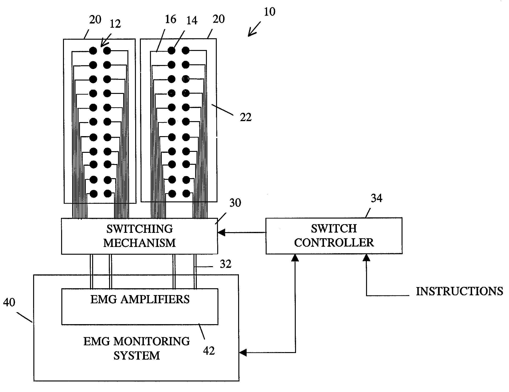
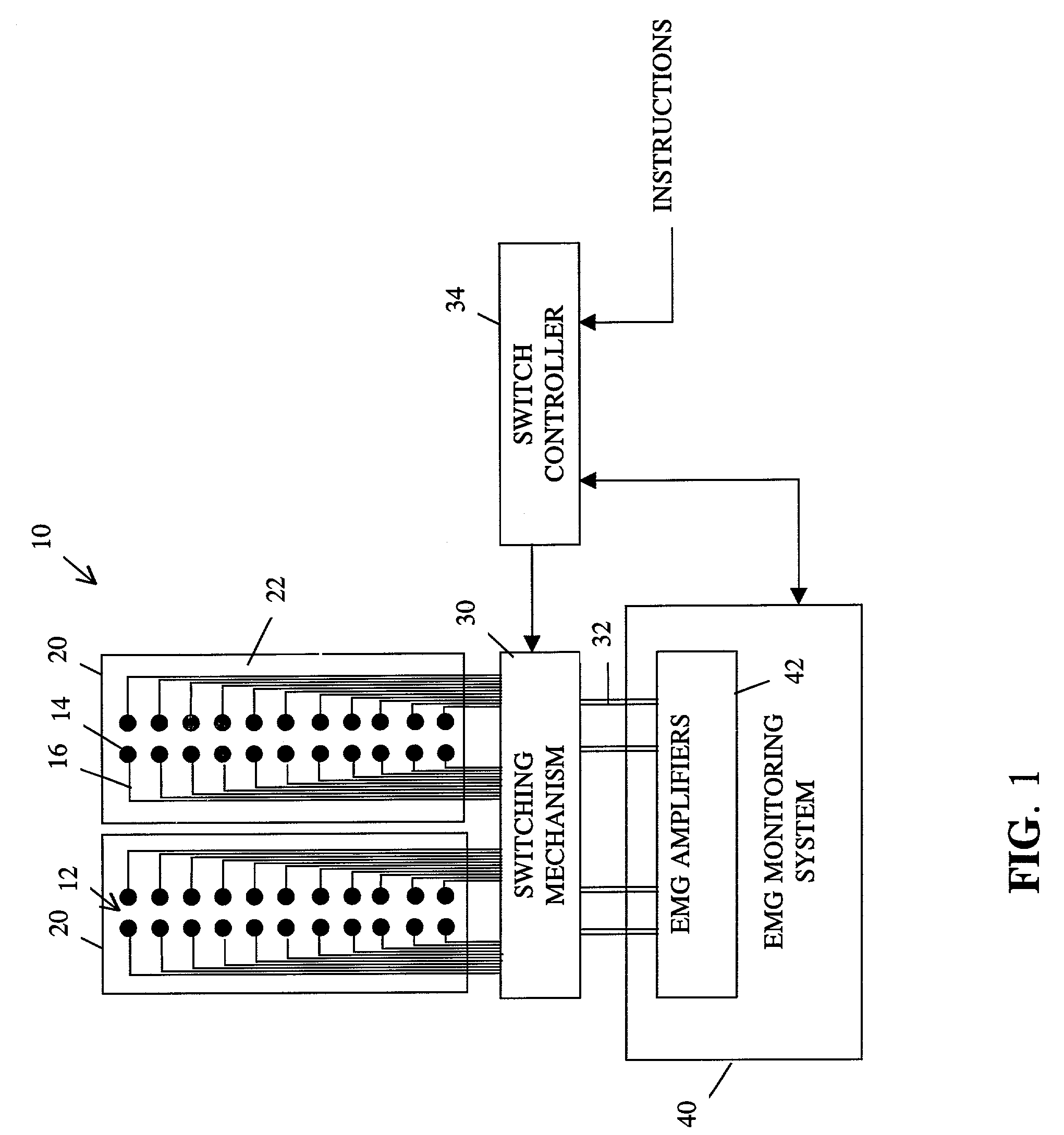
[0017]As depicted in FIG. 1, a matrix 10 includes a plurality of detection electrode arrays 12 that are spaced along two adhesive strips 20. The arrays 12 of electrodes 14 are arranged such that the individual electrodes 14 align with appropriate muscles when the strips are placed essentially vertically on either side of a patient's spine. A plurality of lines 16 electrically connect the electrodes 14 to a switching mechanism 30, which selectively provides the signals from the individual arrays 12 to EMG amplifiers 42 that are included in EMG monitoring instrumentation 40. In the system depicted in the drawing the monitoring instrumentation operates in a conventional manner and includes four EMG amplifiers. Accordingly, the signals from the arrays 12 are switched over four lines 32 to the respective amplifiers 42, such that measurements from two spinal levels can be made simultaneously. If additional EMG amplifiers are included in the EMG monitoring instrumentation, measurements fro...


PUM


Abstract

An EMG monitoring system includes a matrix of detection electrode arrays that is positioned on the patient along his or her spine. The arrays are electrically connected through a switching mechanism to EMG amplifiers that are included in conventional monitoring instrumentation. A switch controller operates the switches to provide signals to the EMG amplifiers from selected sets of detection electrode arrays. The controller controls the switches to provide signals simultaneously to each EMG amplifier. If the monitoring instrumentation includes four EMG amplifiers, the matrix of electrode arrays and the switching mechanism may be used to take simultaneous measurements at two different spinal levels. If additional EMG amplifiers are included, simultaneous measurements at additional spinal levels may also be made. The matrix may also include redundant arrays and / or electrodes, such that the clinician can select the sets of electrodes that conform to the size of the patient.

Description

CROSS-REFERENCE TO RELATED APPLICATIONS[0001]The present application claims the benefit of U.S. Provisional Patent Application Ser. No. 60 / 327,324, which was filed on Oct. 5, 2001, by Lee Richard Brody for a APPARATUS FOR ROUTING ELECTROMYOGRAPHY SIGNALS and is hereby incorporated by reference.BACKGROUND OF THE INVENTION[0002]1. Field of the Invention[0003]The invention relates generally to systems for monitoring electromyography signals.[0004]2. Background Information[0005]Electromyography (EMG) signals are bioelectric signals that are generated during muscle contraction, and the energy of the EMG signals is proportional to muscle tone. Chiropractors and other healthcare clinicians currently monitor surface EMG signals to evaluate paraspinal muscle tone. Each EMG signal is detected using a detection electrode array that is held on the skin above the muscle.[0006]The known prior detection electrode arrays are hand-held devices that include two differential electrodes. A ground elect...

Claims


Application Information

Patent Timeline
Patent Type & Authority Patents(United States)
IPC IPC(8): A61B5/0492A61B5/0488A61B5/296
CPCA61B5/0492A61B5/296
Inventor BRODY, LEE RICHARD
Owner FASSTECH
Why Eureka
Try Eureka