
Internal combustion device and methods of use

Inactive Publication Date: 2005-11-22
HALE JAMES R +1
View PDF6 Cites 12 Cited by
  • Summary
  • Abstract
  • Description
  • Claims
  • Application Information

AI Technical Summary

Benefits of technology

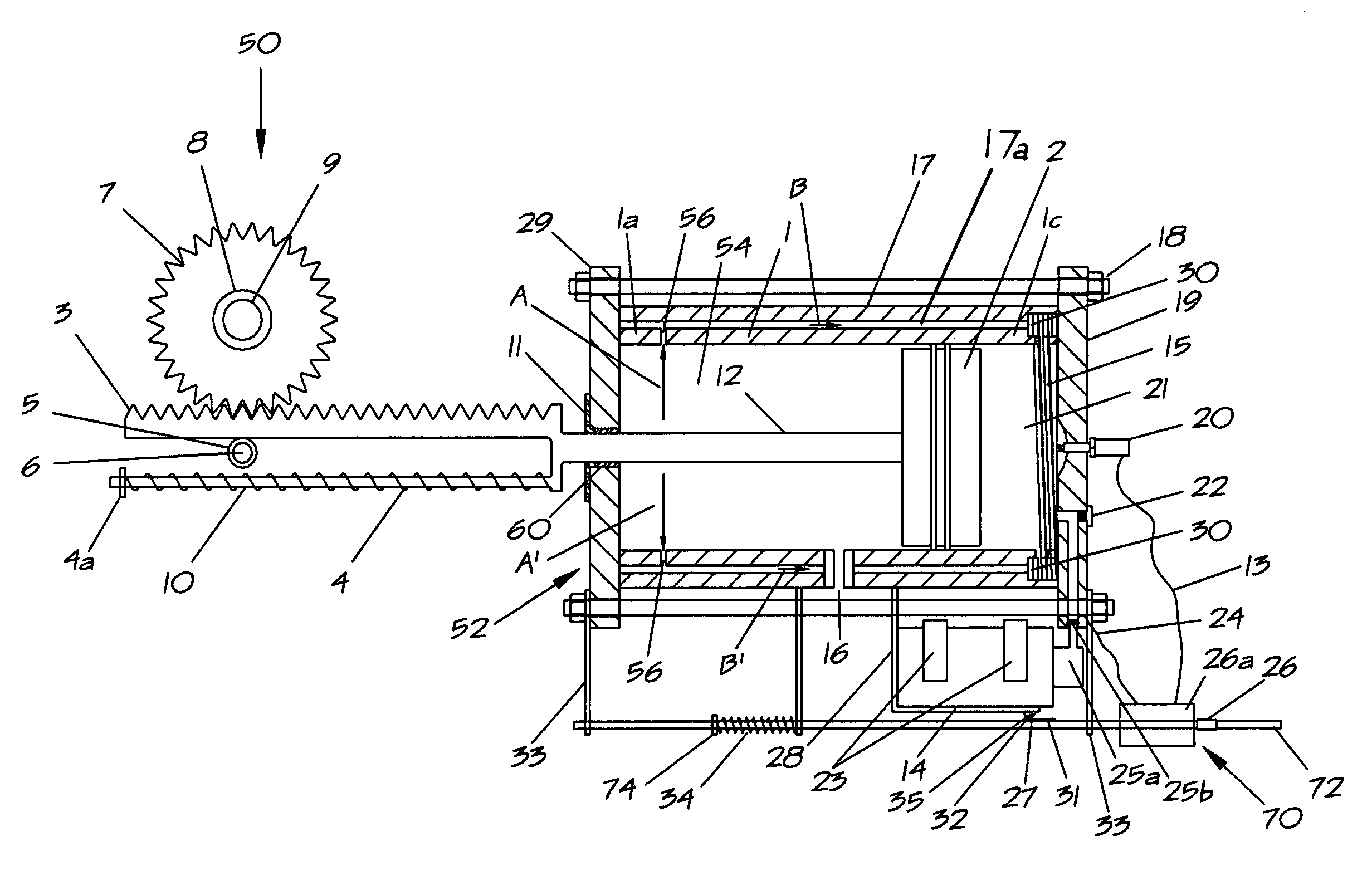
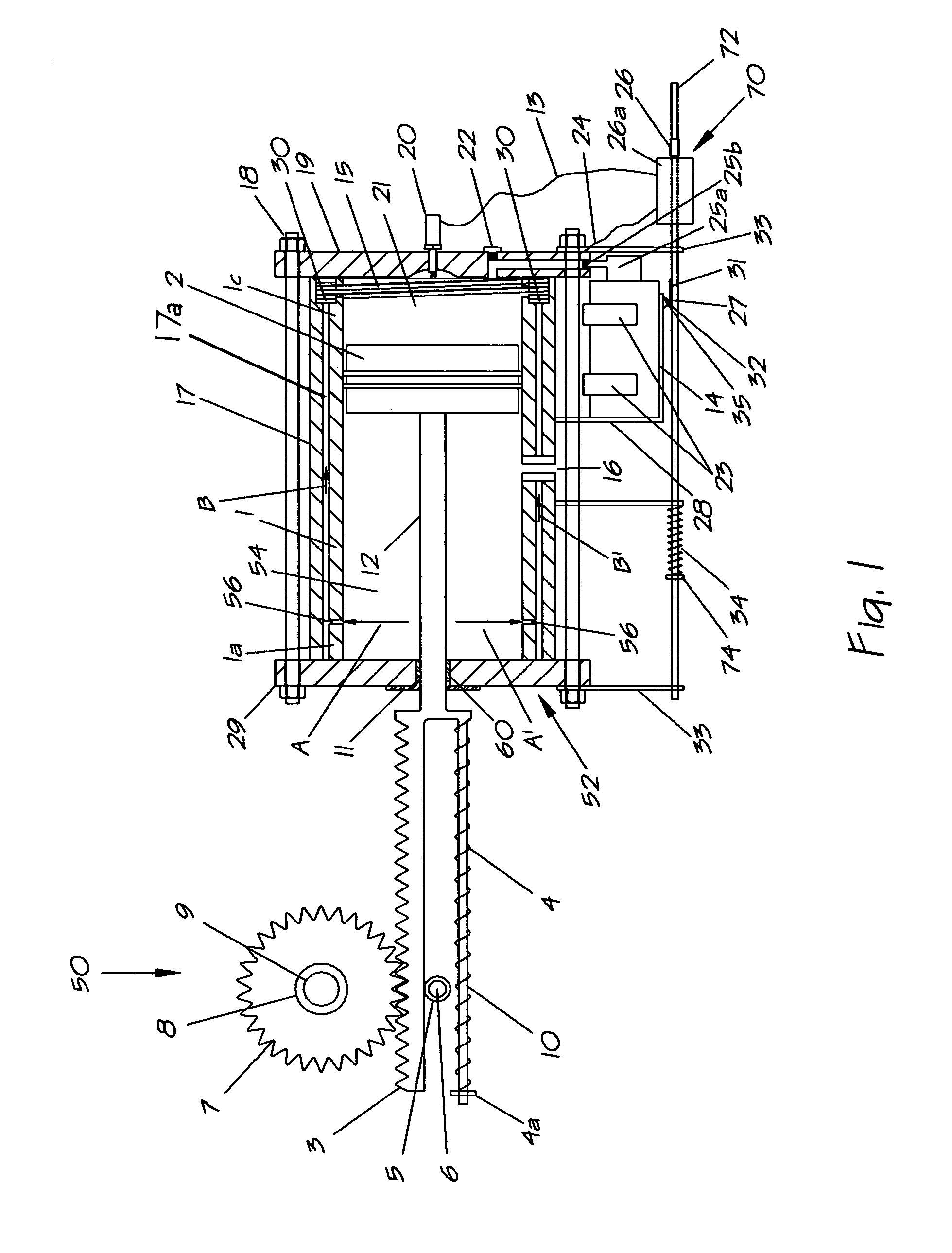
[0006]Our invention provides a simple and inexpensive internal combustion device that is adaptable for rotating an internal combustion engine's crankshaft such that the engine starts. Our device provides a hand-initiated fuel source and igniter that are operationally connected to a cylinder with a piston. Our device fires once, forcing the piston to move a connecting rod that extrudes from the device and is operationally connected to the internal combustion engine's crankshaft, the movement of the connecting rod rotating the crankshaft to the extent necessary to start the engine. Our internal combustion device requires no battery or external electrical power, and is scalable to internal combustion engines of various sizes.

Problems solved by technology

The rope starter requires physical exertion that is unacceptable to many users, while the electric starter requires relatively expensive and complicated apparatus.

Method used


Image

  • Internal combustion device and methods of use
  • Internal combustion device and methods of use
  • Internal combustion device and methods of use

Examples


Embodiment Construction

[0022]The following discussion describes in detail exemplary embodiments of the invention. This discussion should not be construed, however, as limiting the invention to those particular embodiments. Practitioners skilled in the art will recognize numerous other embodiments as well.

[0023]FIGS. 1, 3–7, 11 illustrate an exemplary embodiment of the present invention in cross section. The device 50 cooperates with a fuel subsystem, that is, a replaceable compressed fuel canister 14 that is commercially available. The canister includes its own fuel metering valve 25 and discharge nozzle 25a. This type of canister releases fuel in a gaseous state in response to a slight bending of the discharge nozzle relative to the canister.

[0024]The device 50 includes a frame 52 having a cylinder 1, and a piston 2, the piston being positioned within the cylinder, using conventional rings 76, and dividing the cylinder into a combustion chamber 21 and a purging chamber 54, the cylinder having an upper en...


PUM


Abstract

An internal combustion device is provided for starting a parent engine, the device having a frame having a piston in a cylinder forming a combustion chamber, the frame further having an air passage and a fuel passage for receiving air and fuel into the combustion chamber. A rod connects the piston to a gear train, the gear train being operationally connected to a crankshaft of the parent engine. An ignition mechanism is operationally connected to the combustion chamber for initiating a combustion process using the received fuel and air within the combustion chamber. The piston is driven one power stroke, causing the crankshaft of the parent engine to rotate. A fuel subsystem utilizing a conventional, replaceable compressible fuel canister. Air forced from the cylinder on the piston is routed to the combustion chamber for purging the combustion chamber of spent gases, and mixing with subsequent fuel gas entry.

Description

REFERENCE TO PRIOR APPLICATIONS[0001]This application claims the benefit of the filing date of provisional application 60 / 568,768, filed in the United Stated Patent & Trademark Office on May 5, 2004, by the above-named inventors.BACKGROUND OF THE INVENTION[0002]1. Field of the Invention[0003]The field of the invention is internal combustion engines, and more particularly, the use of a smaller internal combustion device to start a larger internal combustion engine.[0004]2. Description of Related Art[0005]A typical small internal combustion engine, such as that on a lawn mower, has a rope starter that rotates the engine's crankshaft, which starts the engine. Electric starters are also used to rotate the crankshaft for the same purpose. Once the crankshaft is rotated both these starters are separated from the crankshaft. The rope starter requires physical exertion that is unacceptable to many users, while the electric starter requires relatively expensive and complicated apparatus. Wha...

Claims


Application Information

Patent Timeline
IPC IPC(8): F02N17/053F02N17/00F02N7/02F02N19/08
CPCF02N7/02
Inventor HALE, JAMES R.DAVIS, CLIFFORD M.
Owner HALE JAMES R
Learn More