Rainwater collection device

a rainwater collection and rainwater technology, applied in mechanical equipment, roof drainage, transportation and packaging, etc., can solve the problem of not disclosing a new rainwater collection device, and achieve the effects of low manufacturing cost, convenient and efficient manufacturing and marketing, and durable and reliable construction

Inactive Publication Date: 2005-11-22
KUEHNEMAN BRET A
View PDF19 Cites 27 Cited by
  • Summary
  • Abstract
  • Description
  • Claims
  • Application Information

AI Technical Summary

Benefits of technology

[0016]It is another object of the present invention to provide a new rainwater collection device which may be easily and efficiently manufactured and marketed.
[0017]It is a further object of the present invention to provide a new rainwater collection device which is of a durable and reliable construction.
[0018]An even further object of th

Problems solved by technology

While these devices fulfill their respective, particular objectives and requireme

Method used


Image

  • Rainwater collection device
  • Rainwater collection device
  • Rainwater collection device

Examples


Embodiment Construction

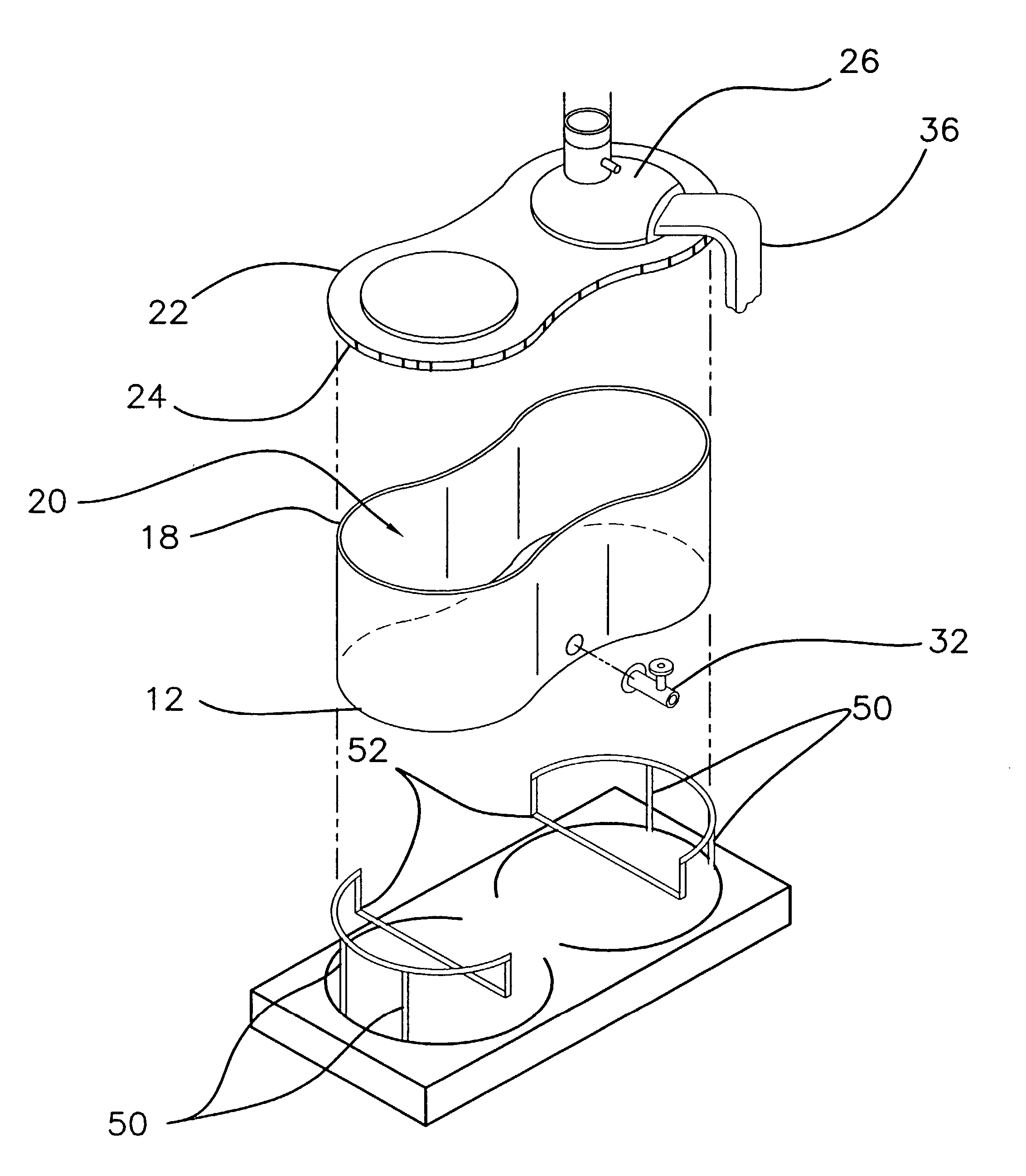
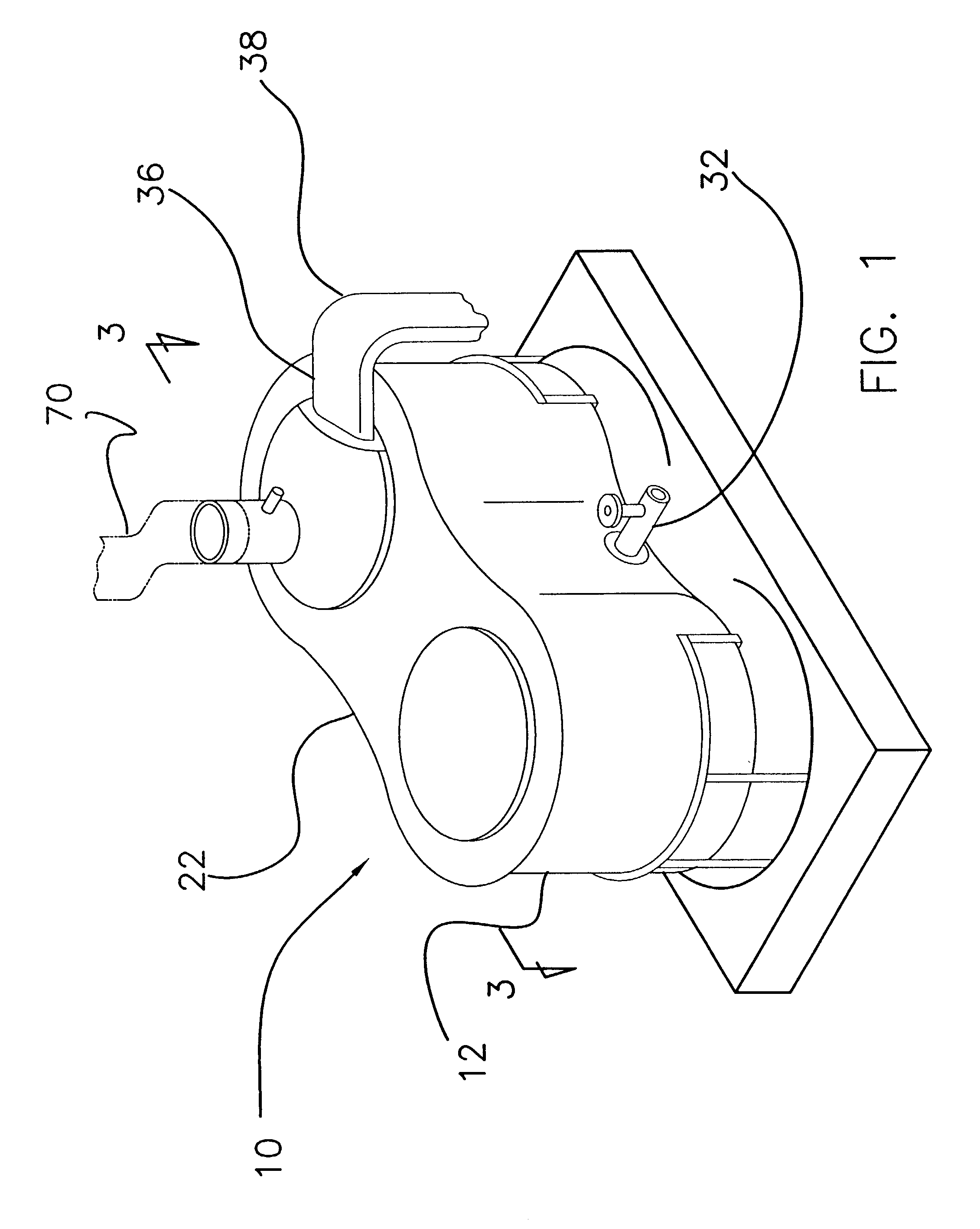
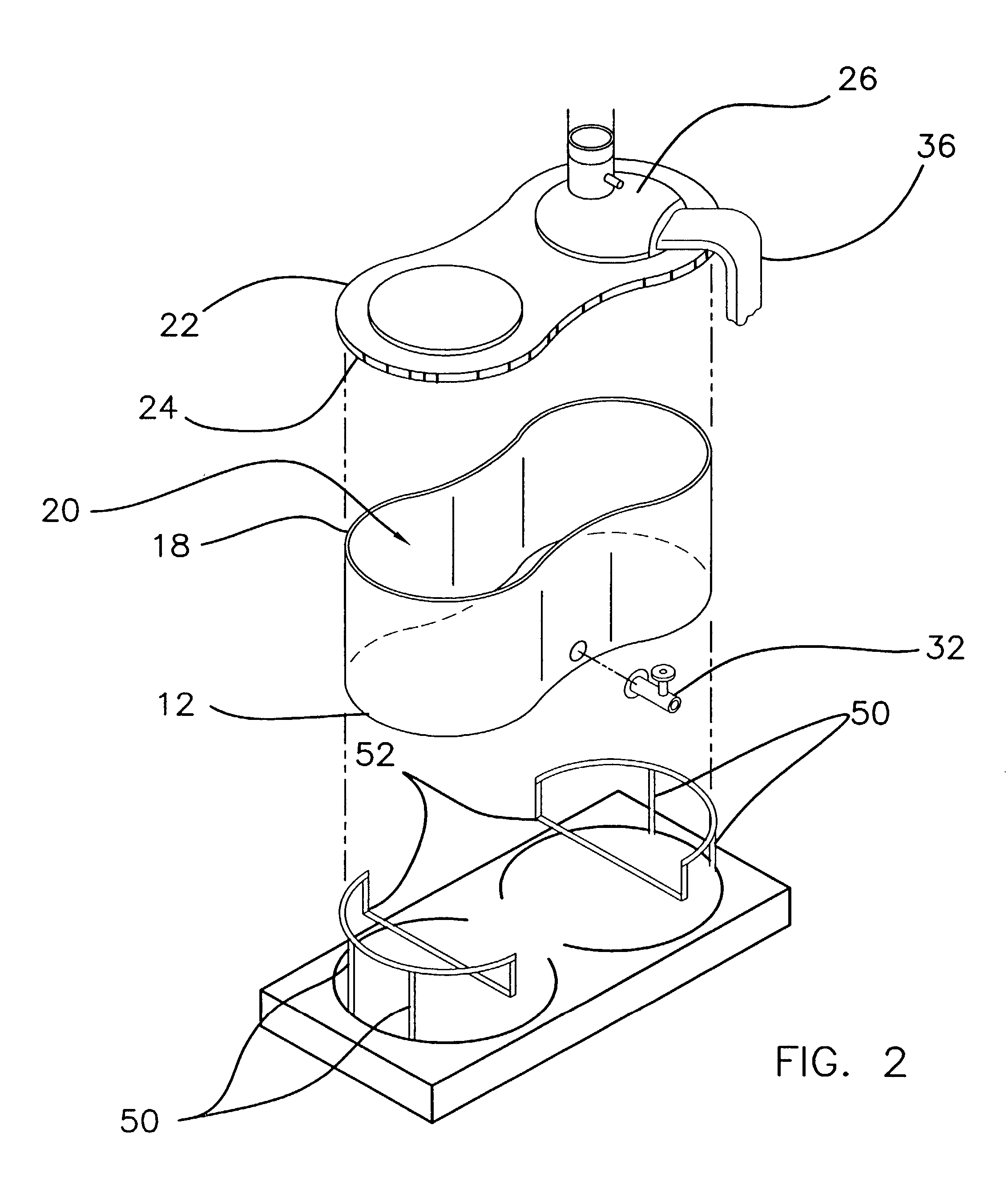
[0030]With reference now to the drawings, and in particular to FIGS. 1 through 5 thereof, a new rainwater collection device embodying the principles and concepts of the present invention and generally designated by the reference numeral 10 will be described.

[0031]As best illustrated in FIGS. 1 through 5, the rainwater collection device 10 generally comprises a housing 12 having a bottom wall 14 and a peripheral wall 16 extending upwardly from the bottom wall 14. The peripheral wall 16 has a top edge 18 defining an opening 20 extending into the housing 12. A top wall 22 defines a cover which positionable on the housing 12 for selectively opening and closing the opening 20 in the housing 12. The top wall 22 has a peripheral flange 24 thereon for extending over the top edge 18 of the peripheral wall 16. The top wall 22 has a convex, or upwardly extending section 26, which extends upwardly away from the bottom wall 14 for reasons which will become readily apparent. A plurality of conven...


PUM


Abstract

A rainwater collection device for collecting rainwater from a gutter for later usage. The rainwater collection device includes a housing having a bottom wall and a peripheral wall extending upwardly from the bottom wall. The peripheral wall has a top edge defining an opening extending into the housing. A top wall defines a cover which is positionable on the housing for selectively opening and closing the opening in the housing. A supply pipe extends through and is attached to the top wall. The supply pipe is removably coupled to the gutter such that water in the gutter may enter the housing through the supply pipe. A drainage pipe is in fluid communication with the housing. The drainage pipe extends into the peripheral wall and is positioned generally adjacent to the bottom wall. A valve is positioned in the drainage pipe for selectively opening and closing the drainage pipe.

Description

BACKGROUND OF THE INVENTION[0001]1. Field of the Invention[0002]The present invention relates to rainwater collectors and more particularly pertains to a new rainwater collection device for collecting rainwater from a gutter for later usage.[0003]2. Description of the Prior Art[0004]The use of rainwater collectors is known in the prior art. More specifically, rainwater collectors heretofore devised and utilized are known to consist basically of familiar, expected and obvious structural configurations, notwithstanding the myriad of designs encompassed by the crowded prior art which have been developed for the fulfillment of countless objectives and requirements.[0005]Known prior art includes U.S. Pat. No. 5,730,179; U.S. Pat. No. 5,863,151; U.S. Pat. No. 5,873,383; U.S. Pat. No. 5,490,538; U.S. Pat. No. 3,730,120; and U.S. Des. Pat. No. 335,744.[0006]While these devices fulfill their respective, particular objectives and requirements, the aforementioned patents do not disclose a new ...

Claims


Application Information

Patent Timeline
IPC IPC(8): E03B3/02E03B3/00E03B3/03E04D13/08
CPCE03B3/03E04D13/08E04D2013/0806E04D2013/0853E04D2013/0873Y02A20/00Y02A20/108Y10T137/6969Y10T137/7039Y10T137/86308
Inventor KUEHNEMAN, BRET A.
Owner KUEHNEMAN BRET A
Why Eureka
Try Eureka