Spring-loaded tube squeezing device

Inactive Publication Date: 2005-11-22
TORBET ERIC
View PDF9 Cites 30 Cited by
  • Summary
  • Abstract
  • Description
  • Claims
  • Application Information

AI Technical Summary

Benefits of technology

[0011]Accordingly, several objects and advantages of the present invention are to provide a portable tube squeezing device which is of simple and economical construction, for which the tube can be inserted and extracted quickly and easily, which alleviates the user of the need to manually squeeze the tube, which retains a clamped position along the tube thereby preventing back-flow of tube contents, which requires relatively little force to advan

Problems solved by technology

Many of these suffer, however, from being excessively complex and uneconomical to produce.
Some simple devices work by winding the tube with a key, but these do not function well with plastic tubes which are resilient and tend to unwind.
Furthermore, most devices of this type have the added inconvenience of requiring the tube to be subsequently unwound in order to disengage the key from the tube.
A major disadvantage of this type of device, however, is that the slit width is fixed and therefore not appropriate for all tube wall thicknesses.
However, the device does not function well with plastic tubes which due to their resiliency are not amenable to crimping, and thus back-flow of the tube contents can occur if the handles are released.
Additionally, the teeth of the rollers can cause tears in plastic tubes if excessive force is applied.
A further disadvantage of the device of Gill, true for all types of tubes squeezed, is that the user must continuously squeeze the handles together as the device advances forward, a fact which may cause difficulty or be an inconvenience for some individuals.
Although the user is alleviated of the task of squeezing, no easy mean

Method used


Image

  • Spring-loaded tube squeezing device
  • Spring-loaded tube squeezing device
  • Spring-loaded tube squeezing device

Examples


Embodiment Construction

—DESCRIPTION

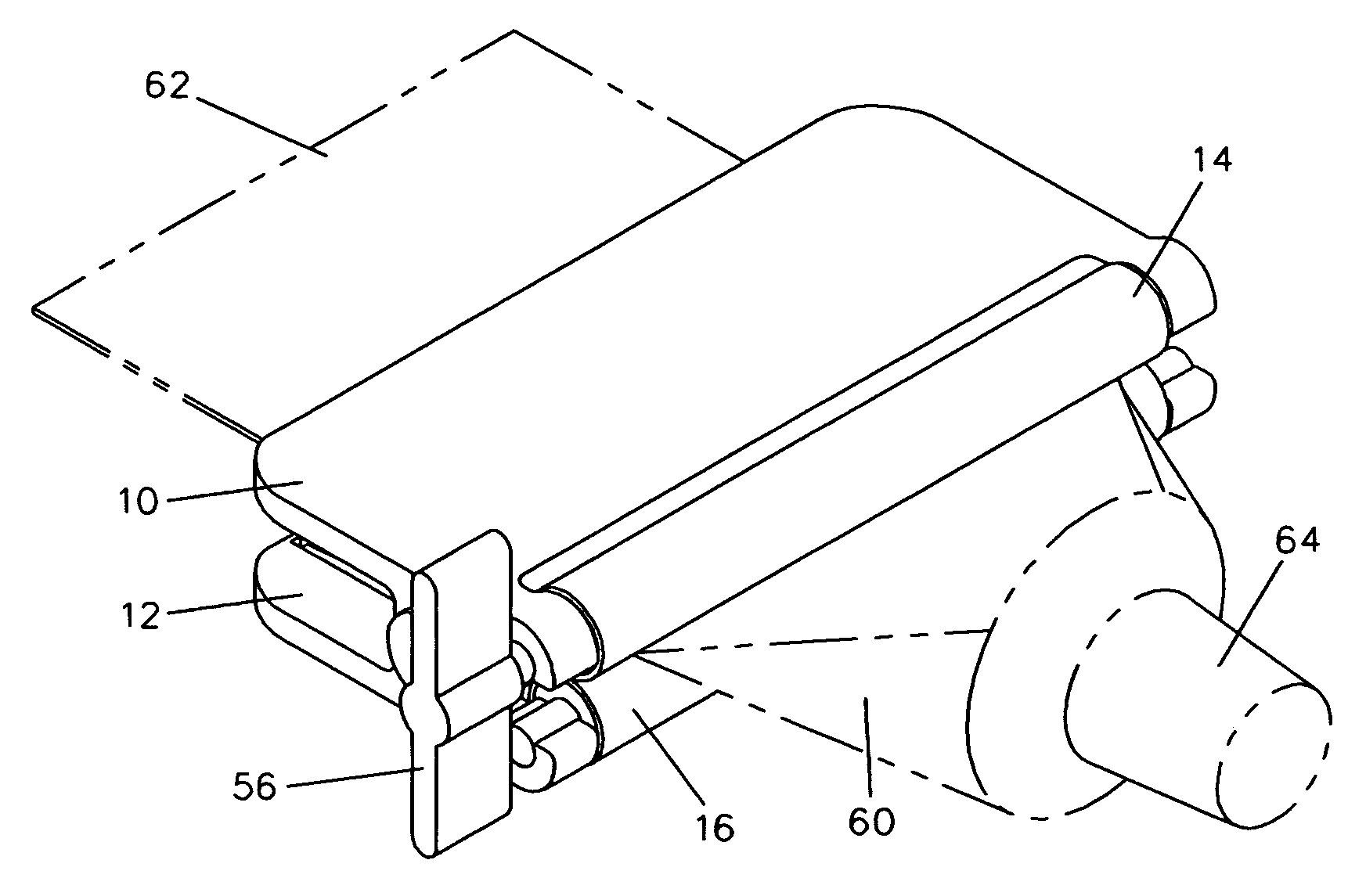
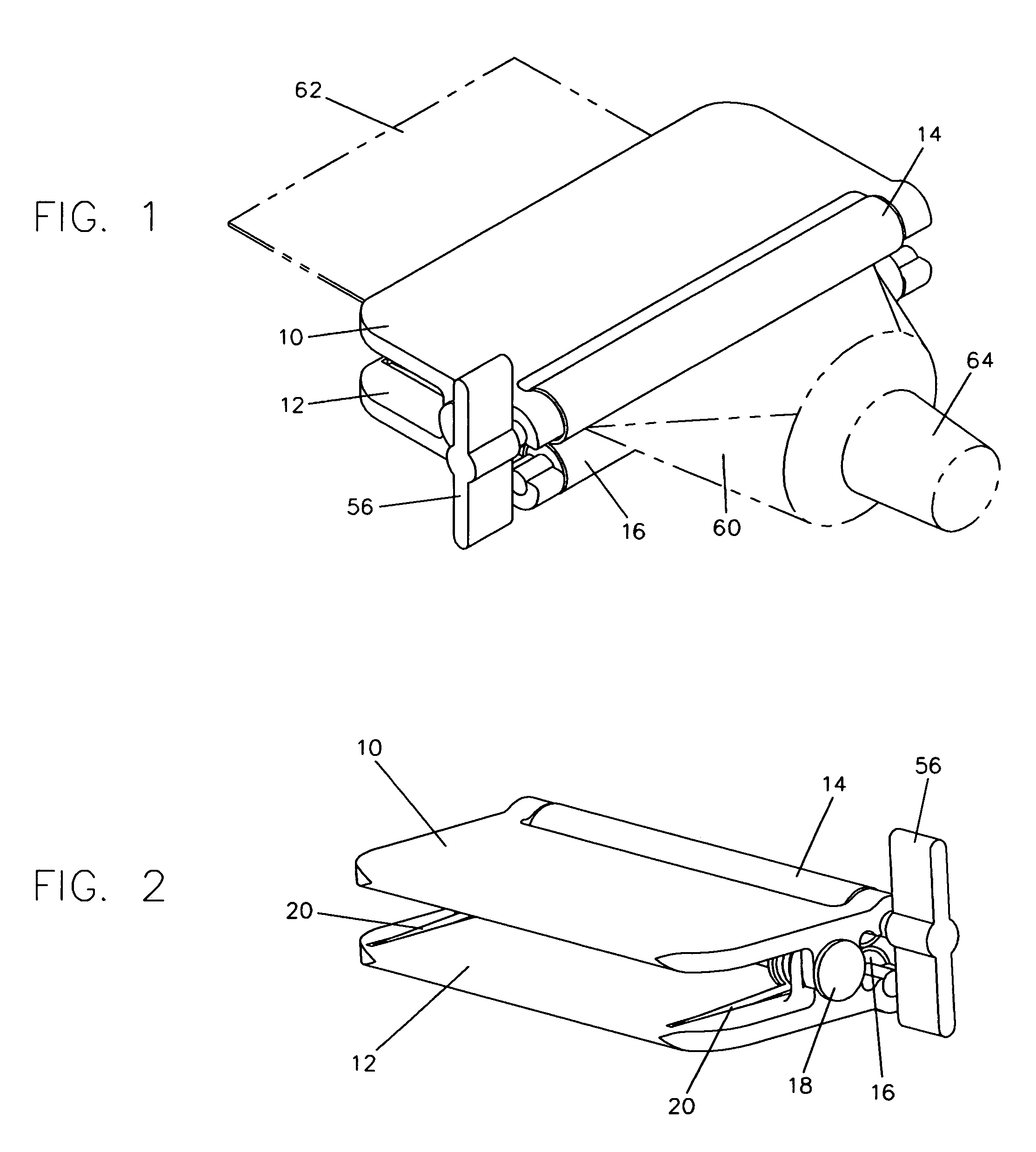
[0040]FIG. 1 shows a perspective view of a preferred embodiment of the tube squeezing device, along with a collapsible tube 60 with a crimped end 62 and a nozzle end 64 drawn in phantom and inserted in the proper orientation for use. FIG. 2 shows the tube squeezing device alone from a different perspective angle. Referring now to these two figures, the tube squeezing device consists of two identical opposed lever handles 10 and 12, attached together by two pintles 18. Only one pintle is shown in the figures, the other one being in mirror opposition to the one shown. Lever handles 10 and 12 are free to rotate about pintles 18. Pintles 18 additionally serve as pivots or anchors for two torsional springs 20. These springs have arms extending onto lever handles 10 and 12 for leverage. In the orientation of lever handles 10 and 12 shown in these figures, the arm extensions of torsional springs 20 are approximately parallel and the springs are in a torqued state. Forward of th...


PUM


Abstract

A device for squeezing various household collapsible tubes comprises two lever handles, two pintles, two torsional springs, a primary roller, and a secondary roller. The lever handles are held together by and are free to rotate about the two pintles, forming a double non-crossing class 1 lever arrangement. The rollers, held in gudgeons by snap fit, are also free to rotate. The primary roller is distinguished from the secondary roller by having a crank at one end. The torsional springs, anchored by the pintles, provide a torque which causes the two rollers to clamp together. Operation of the tube squeezing device proceeds by inserting the crimped end of a collapsible tube between the rollers and turning the crank, thereby turning the rollers so as to squeeze the tube flat and to push its contents toward the nozzle end. Insertion and extraction of the tube is effected most readily by applying a compressive force to the two lever handles, creating a gap between the rollers for the tube to easily pass through.

Description

BACKGROUND[0001]1. Field of Invention[0002]This invention relates generally to devices for squeezing and expelling the contents of collapsible tubes, and specifically to such devices having rollers and being small and economical in construction.[0003]2. Description of Prior Art[0004]Thin-walled collapsible tubes have long been popular as containers for items such as toothpaste, cream, and other paste-like materials. A great number of devices have been invented to squeeze and expel the contents of such tubes. Many of these suffer, however, from being excessively complex and uneconomical to produce.[0005]Some simple devices work by winding the tube with a key, but these do not function well with plastic tubes which are resilient and tend to unwind. Furthermore, most devices of this type have the added inconvenience of requiring the tube to be subsequently unwound in order to disengage the key from the tube.[0006]Other devices expel the tube contents without requiring the tube to be wo...

Claims


Application Information

Patent Timeline
IPC IPC(8): B65D35/24B65D35/28
CPCB65D35/285
Inventor TORBET, ERIC
Owner TORBET ERIC
Why Eureka
Try Eureka