Flush valve device of flush toilet

Inactive Publication Date: 2005-11-22
TOTO LTD
View PDF15 Cites 33 Cited by
  • Summary
  • Abstract
  • Description
  • Claims
  • Application Information

AI Technical Summary

Benefits of technology

[0004]The object of the present invention is thus to solve the drawbacks of the prior art technique and to provide a flush valve device of a flush toilet that has the

Problems solved by technology

The restricted positions of the rotating handle 304 and the flush valve body 312 may lower the operabili

Method used


Image

  • Flush valve device of flush toilet
  • Flush valve device of flush toilet
  • Flush valve device of flush toilet

Examples


first embodiment

A. First Embodiment

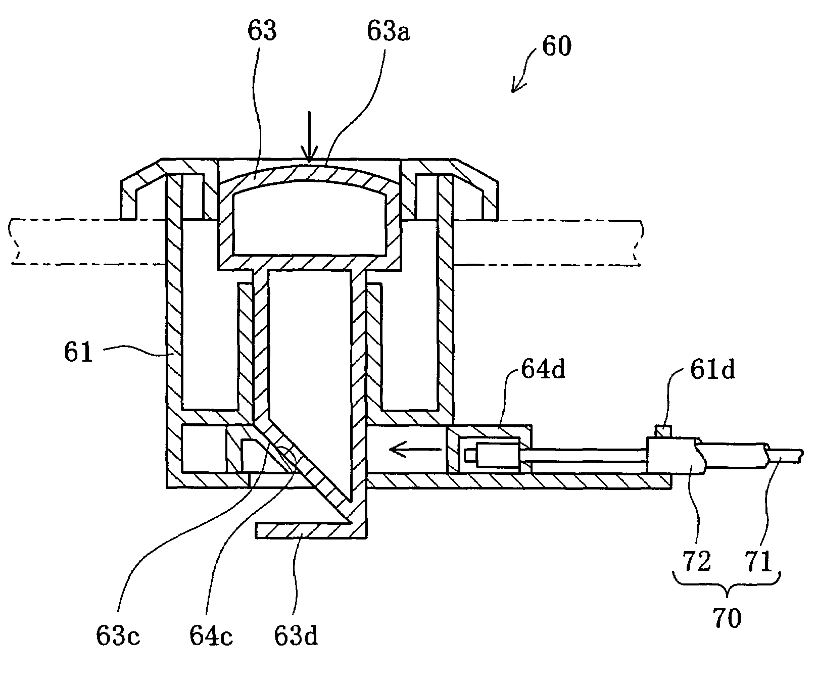
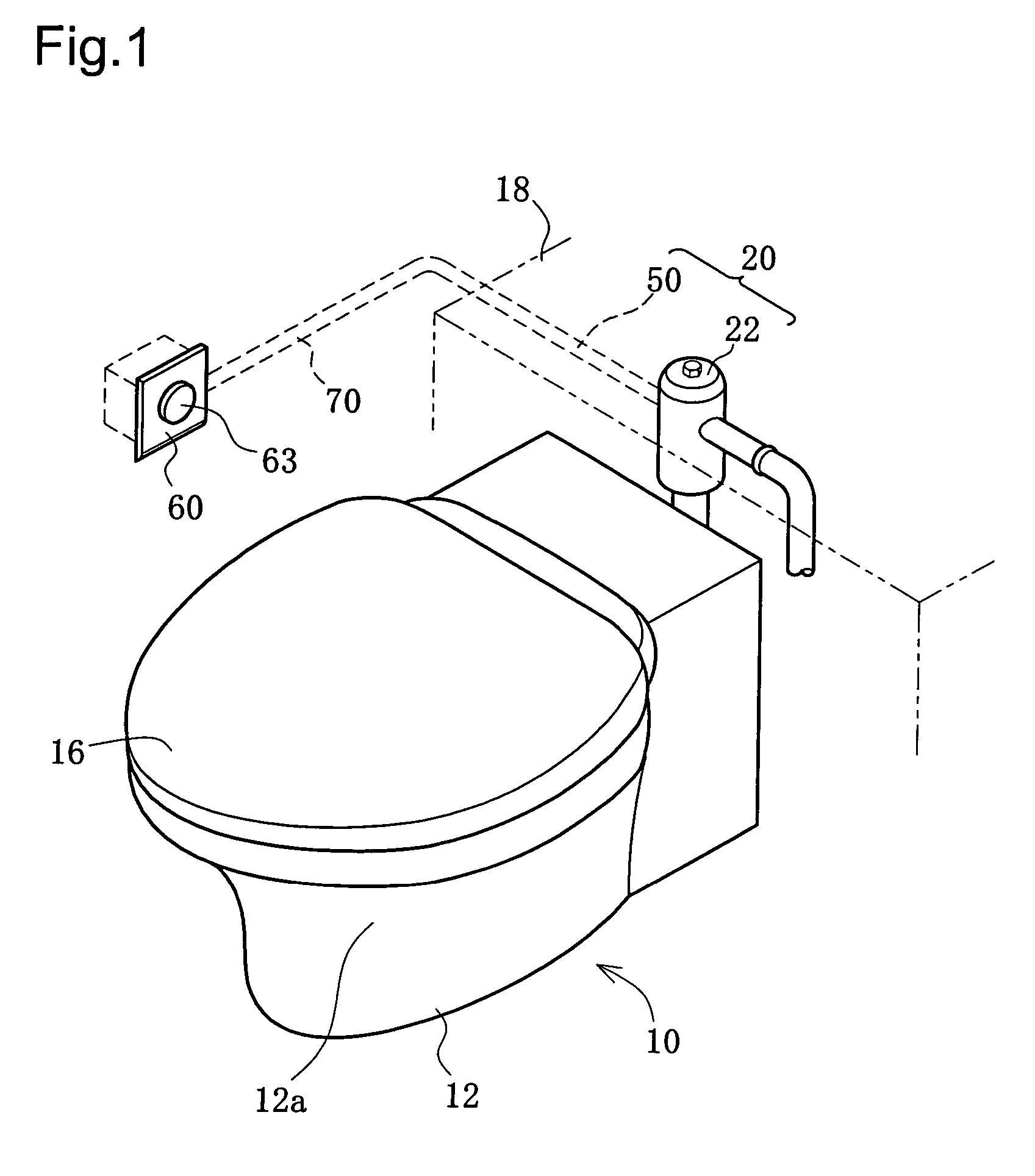
[0069]FIG. 1 illustrates the periphery of a flush toilet 10 equipped with a flush valve device in a first embodiment of the present invention. As shown in FIG. 1, the flush toilet 10 has a toilet body 12 including a bowl section 12a. A toilet seat 16 is attached in an openable and closable manner to the upper face of the bowl section 12a. A cabinet 18 is located in the rear side of the toilet body 12, and a flush valve device 20 is disposed in the cabinet 18. The flush valve device 20 has a flush valve body 22 connected to a city water source and an operation unit 50 used to activate and operate the flush valve device 20.

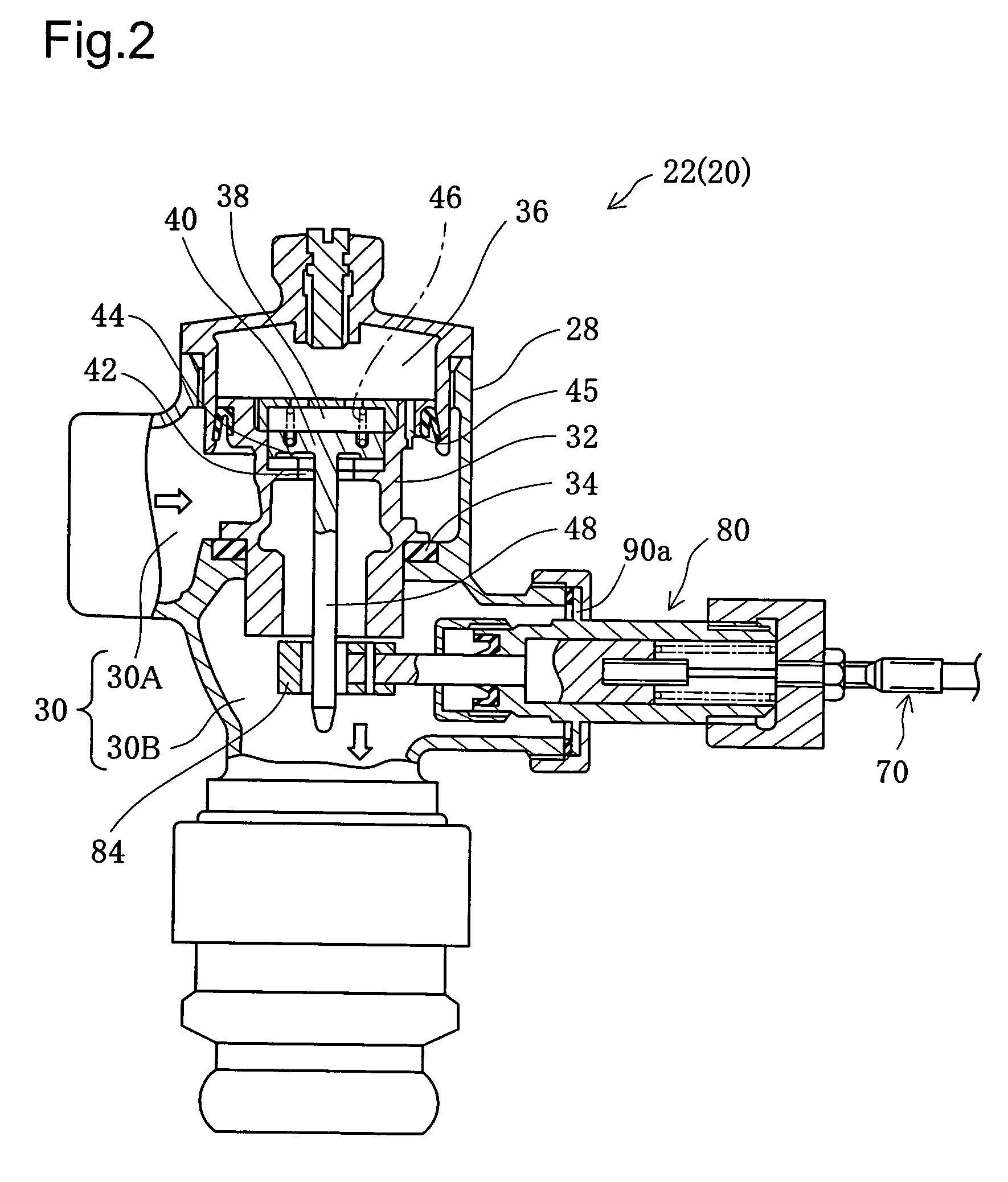
[0070]FIG. 2 is a sectional view illustrating the periphery of the flush valve body 22. As shown in FIG. 2, the flush valve body 22 has a main water conduit 30 constructed inside a casing 28. A main valve 32 is disposed in the main water conduit 30 to open and close the main water conduit 30. Seating of the main valve 32 on a valve seat 34 disconn...

second embodiment

B. Second Embodiment

[0094]FIG. 8 is a front view illustrating a flush valve device 100 in a second embodiment. The flush valve device 100 includes a wall fixation frame 110 that is attached to a fixation recess WLa formed in a bathroom wall WL (partition wall) and defines an inspection opening 114, a cover panel 120 that is detachably attached to a front face of the wall fixation frame 110, a flush valve body 141 that is disposed in a rear space of the bathroom wall WL, and a valve actuation unit 160 that functions to open and close the flush valve body 141. The valve actuation unit 160 has an auto water flow mechanism 161 activated by a built-in sensor and a manual operation unit 170 activated by manual operations. The manual operation unit 170 includes a button unit 171, a tilting mechanism 180, and a cable mechanism 190.

[0095]In response to a detection of a detachment action of the human body by the built-in sensor of the auto water flow mechanism 161, the flush valve body 141 is...

modified example 1

(7)-1. Modified Example 1

[0136]A tilting mechanism 180B shown in FIG. 25 includes a support fixture 187B and a pivot lever 188B (pressing force conversion member) supported on one end of the support fixture 187B in a pivotally rotatable manner. The inner cable 191 is linked with the other end of the pivot lever 188B. In response to a pull of the inner cable 191 in the direction of an open arrow, the pivot lever 188B rotates about a pivot 188Bc to press the pressure bar 182.


PUM


Abstract

A flush valve device 20 of a flush toilet includes a flush valve body 22 connected to a city water source and an operation unit 50. The operation unit 50 has an operation button 63 and a flexible inner cable 71, which is part of a cable mechanism 70. The inner cable 71 is extended from a rear side to a lateral side of a toilet body 12 and is linked with the operation button 63. In response to a press of the operation button 63, the flush valve body 22 opens to make a supply of washing water flown into the toilet body 12. This arrangement desirably increases the degree of freedom in positioning of the flush valve body and the operation unit, enhances the operability of the flush valve device 20, and effectively facilitates installation of the flush valve device 20.

Description

TECHNICAL FIELD[0001]The present invention relates to a flush valve device of a flush toilet and more specifically pertains to an operation unit and an installation mechanism.BACKGROUND ART[0002]A prior art flush valve device is disclosed, for example, in JAPANESE PATENT LAID-OPEN GAZETTE No. 11-324061. FIG. 32 illustrates a rear portion of a flush toilet with a prior art flush valve device mounted thereon. As shown in FIG. 32, a flush valve device 310 connected to a city water source is located in the rear portion of a flush toilet 300. The flush valve device 310 includes a flush valve body 312 and an operation unit 320 that is used to open and close the flush valve body 312. The flush valve body 312 has a main valve to open and close a main water conduit and a pilot valve to lower the water pressure in a back pressure chamber and thereby open the main valve. The operation unit 320 functions to incline a driving rod of the pilot valve, so that a supply of washing water is flown int...

Claims


Application Information

Patent Timeline
IPC IPC(8): E03D3/00E03D3/04F16K31/44F16K31/46
CPCE03D3/04F16K31/465Y10T137/8359
Inventor ENOMOTO, KAZUYUKITANI, JYUNICHINAGANO, KATSUHIKOKOBA, AKIHIKO
Owner TOTO LTD
Why Eureka
Try Eureka