Ink jet cartridge

a technology ink cartridges, applied in printing and other directions, can solve the problem of becoming impossible to continue the suction and achieve the effect of restoring the performance of ink jet cartridges

Inactive Publication Date: 2005-11-22
CANON KK
View PDF3 Cites 12 Cited by
  • Summary
  • Abstract
  • Description
  • Claims
  • Application Information

AI Technical Summary

Benefits of technology

[0006]The present invention was made to solve the above described problem, and its primary object is to provide a reliable ink jet cartridge of a pit-stop ink refill type, which is reliable in that its gas-permeable member is less likely to be deteriorated by the repetition of the cartridge suction necessary for refilling the ink jet cartridge and restoring the performance of the ink jet cartridge, and therefore, less likely to leak ink due to the deterioration of the gas-permeable member, and also to provide an ink jet recording apparatus employing such an ink jet cartridge.
[0014]a suctioning means connectible to the recording head to restore the performance of the recording head by suction.

Problems solved by technology

Thus, as the body of ink having been suctioned into the ink jet cartridge reaches the gas-permeable member, it becomes impossible to continue the suction of the ink jet cartridge.

Method used


Image

  • Ink jet cartridge
  • Ink jet cartridge
  • Ink jet cartridge

Examples


embodiment 1

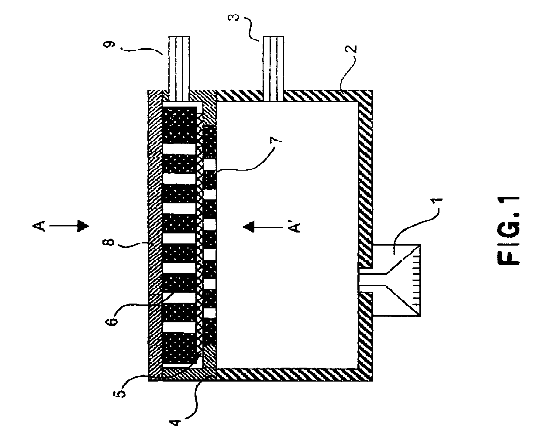
[0028]FIG. 1 is a sectional view of the ink jet cartridge in the first embodiment of the present invention.

[0029]Designated by a referential numeral 1 is an ejection unit for liquid ejection. As the recording head becomes clogged with ink, the liquid ejection orifices of the recording head are capped with a suction cap, that is, a head cap. Designated by a referential numeral 2 is a liquid storage chamber in which the liquid to be supplied to the ejection unit is stored (hereinafter, the liquid to be ejected from the recording head in this embodiment will be referred to as ink). The liquid storage chamber 2 is filled with a piece of absorbent substance (unknown) for absorbing ink and retaining it therein. A referential numeral 3 designates a liquid inlet to be connected with a main liquid container (unshown), and a referential numeral 4 designates an intermediary lid for sealing the liquid storage chamber 2. A referential numeral 5 designates a gas-permeable member, and a referentia...

embodiment 2

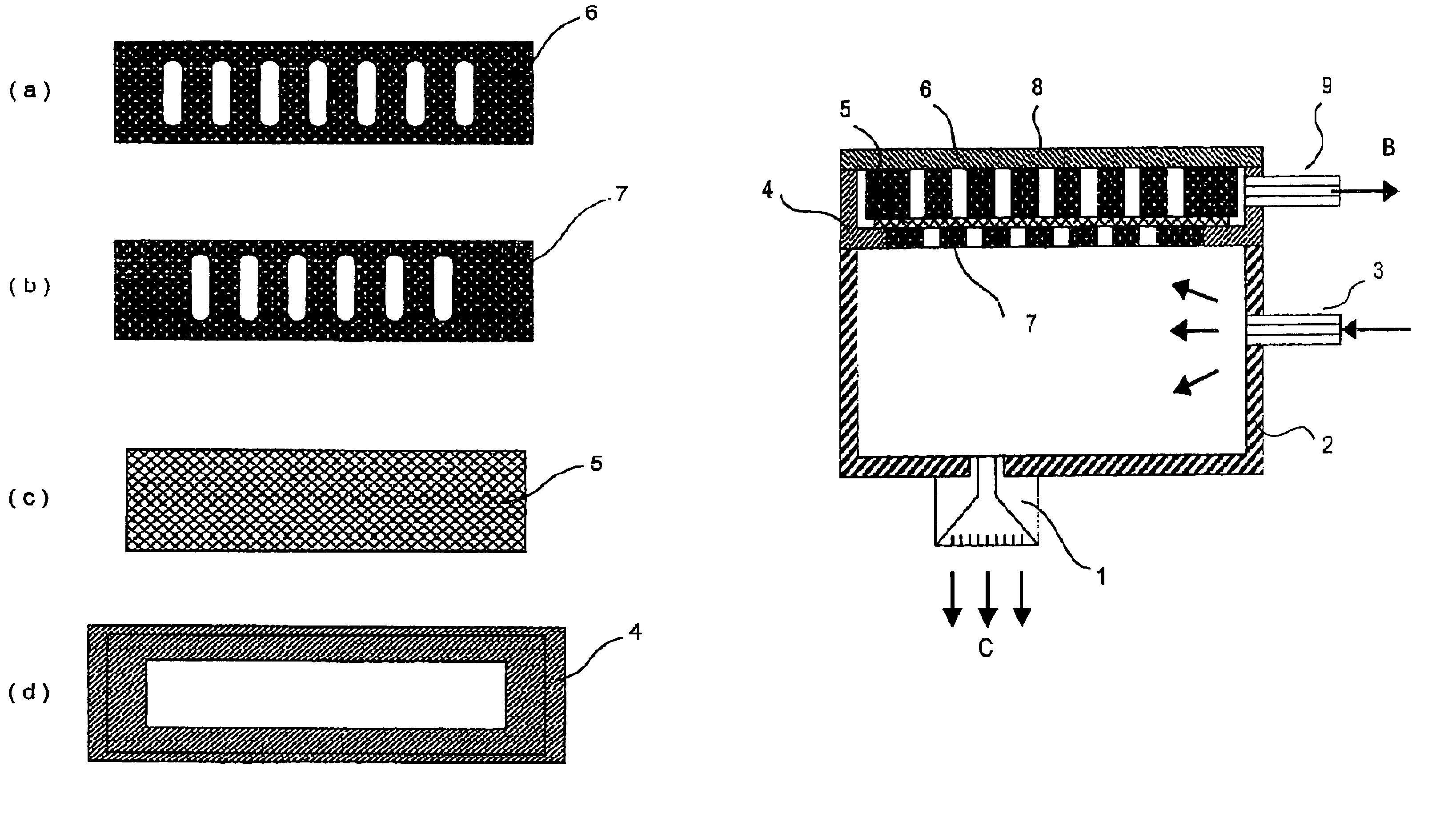
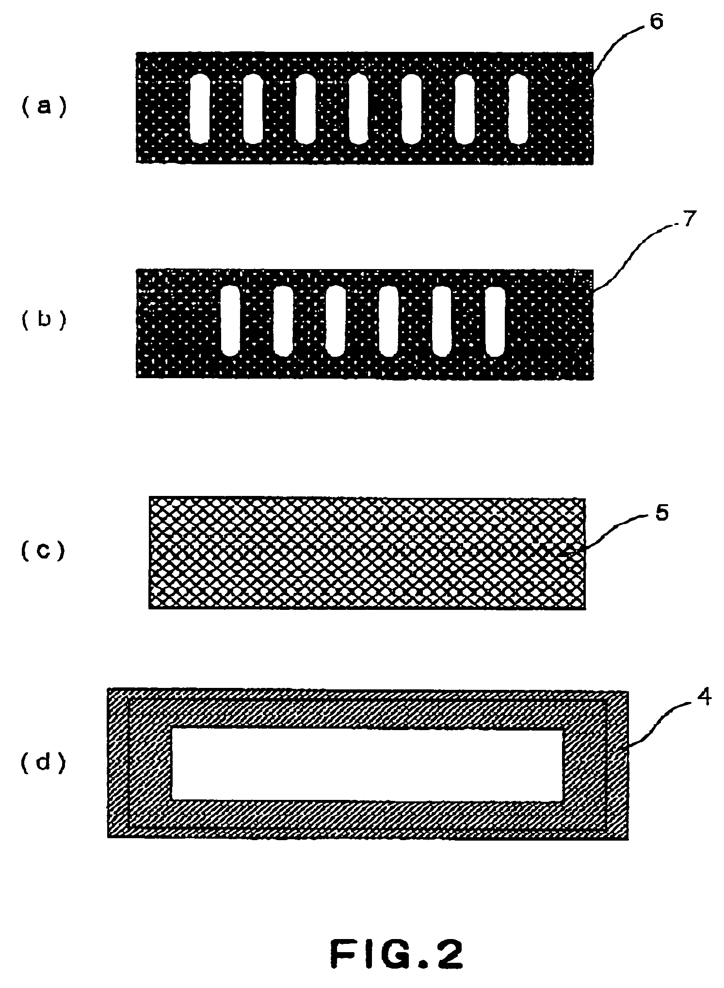
[0037]The sectional view of the ink jet cartridge in this second embodiment of the present invention is similar to the sectional view of the ink jet cartridge shown in FIG. 1; the ink jet cartridge in this embodiment is virtually the same as that in the first embodiment, except for the configurations of the gas-permeable member holding members 6 and 7. FIGS. 5(a)–5(d) show various patterns feasible as the configuration for the gas-permeable member holding member 6 or 7, as seen from the direction indicated by the arrow mark A or an arrow mark A′ in FIG. 1.

[0038]The gas-permeable member holding member 6 shown in FIG. 5(a) is not provided with a hole, but is formed of porous material, allowing thereby gaseous substance to easily pass through it.

[0039]The gas-permeable member holding member 6 shown in FIG. 5(b) has elongated holes which extend in the lengthwise direction of the ink jet cartridge.

[0040]The gas-permeable member holding member 6 shown in FIG. 5(c) has a compound hole, whi...

embodiment 3

[0046]FIG. 7 is a schematic sectional view of the ink jet cartridge in the third embodiment of the present invention.

[0047]Designated by a referential numeral 1 is an ejection unit for liquid ejection, and designated by a referential numeral 2 is a liquid storage chamber in which the liquid to be applied to the ejection unit is stored (hereinafter, the liquid to be ejected from the recording head in this embodiment will be referred to as ink). The liquid storage chamber 2 is filled with a piece of absorbent substance (unshown) for absorbing ink and retaining it therein. A referential numeral 3 designates a liquid inlet to be connected with a main liquid container (unshown) and a referential numeral 4 designates an intermediary lid for keeping the liquid storage chamber 2 virtually sealed. A referential numeral 5 designates a gas-permeable member, and a referential numeral 6 designates a holding member for holding down the gas-permeable member 5, and a referential numeral 7 designate...


PUM


Abstract

An ink jet cartridge includes an ink jet recording head; an ink container for containing ink to be supplied to the recording head; an ink supply source connecting portion which is provided in the ink container and which is connectable with an ink supply source to permit filling of the ink into the ink container; a pressure reduction source connecting portion connectable with a pressure reduction source for reducing pressure in the ink container to permit filling of the ink; an absorbing material provided in the ink container, the absorbing material is capable of retaining the ink and functioning as a negative pressure source for the recording head; a gas-liquid separating member which is disposed between the absorbing material and the pressure reduction source connecting portion and which has a gas permeability and liquid penetration resisting property; and supporting members, disposed at respective sides of the gas-liquid separating member, for supporting the gas-liquid separating member.

Description

FIELD OF THE INVENTION AND RELATED ART[0001]The present invention related to an ink jet cartridge comprising: a recording head which records an image by ejecting ink; and an ink container in which the ink to be supplied to the recording head is stored. It also relates to an ink jet recording apparatus employing such an ink jet cartridge. In particular, it relates to an ink jet cartridge reliable in that it is structured so that its ink container can be reliably refilled with ink as necessary, and also, so that the performance of its recording head can be reliably restored as necessary, and also, it relates to an ink jet recording apparatus employing such an ink jet cartridge.[0002]From the standpoint of reducing ink jet printer size, and also, the standpoint of reducing the load which is borne by the carriage of a printer, various proposals have been made. One of such proposals regards a method in which an ink jet cartridge is intermittently refilled with ink (which hereinafter may ...

Claims


Application Information

Patent Timeline
Patent Type & Authority Patents(United States)
IPC IPC(8): B41J2/175
CPCB41J2/17509B41J2/17513B41J2/17556
Inventor ISHIZAKI, AKEMI
Owner CANON KK
Why Eureka
Try Eureka