Method and apparatus for positioning a top block assembly and neck finish components of a blow molding machine

Active Publication Date: 2005-11-22
ULTRASEAL TECH
View PDF10 Cites 6 Cited by
  • Summary
  • Abstract
  • Description
  • Claims
  • Application Information

AI Technical Summary

Benefits of technology

[0018]A top block assembly is provided that allows adjustment of the positions of the neck finish components to reduce or eliminate fuzz or roughness in the neck portion of a blown container made with the top block assembly. By providing a top block assembly in which the neck finish components can be precisely aligned, wear on the neck finish components as well as other parts of the molding assembly can be greatly reduced. A method of positioning the neck finish components with respect to a top block half is also provided. The method allows the positioning of the components with respect to the front face of the top block half with great precision.
[0023]A top block assembly that reliably maintains the position of a top block half with respect to the parting face of a main mold half is further provided. The assembly includes a top block half, a heel, and a rotatable cam positioned between the top block half and the heel. The cam includes a plurality of flat surfaces and engages the heel, thereby maintaining the top block half in a fixed position with respect to the main mold half and back plate. In order to provide additional stability, a shim is provided on each side of the cam. The shims engage the heel and top block. Such shims can be employed whether the cam has flat surfaces or is smoothly curved.

Problems solved by technology

Such tapping and rigid engagement, usually by steel bolts driven into threaded holes in the main mold, may cause damage and wear to the mold system, particularly when performed repeatedly as is common.
During molding, portions of the parison extending beyond the mold cavity are trapped between the paring faces of the mold halves and become unwanted flash.
Failure to do so can prevent the mold from closing properly, leading to damage or even destruction of the neck finish components and / or blow pin.
Misalignment of the main mold and top block parting faces can result in other problems during attempted molding.
In addition to damaging the neck finish component, unusual and hastened wear of the parting faces, excessive and untrimmable molding flash, concentrated and extreme pressures on areas of the mold and improper shearing of the container opening may occur.
This fact creates a problem and burden when main mold reconditioning or repair is required.
This is a costly and time consuming process.
Movement of the shear steel towards the axis of the blow molding station is said to take up wear that has occurred in the shear steel.

Method used


Image

  • Method and apparatus for positioning a top block assembly and neck finish components of a blow molding machine
  • Method and apparatus for positioning a top block assembly and neck finish components of a blow molding machine
  • Method and apparatus for positioning a top block assembly and neck finish components of a blow molding machine

Examples


second embodiment

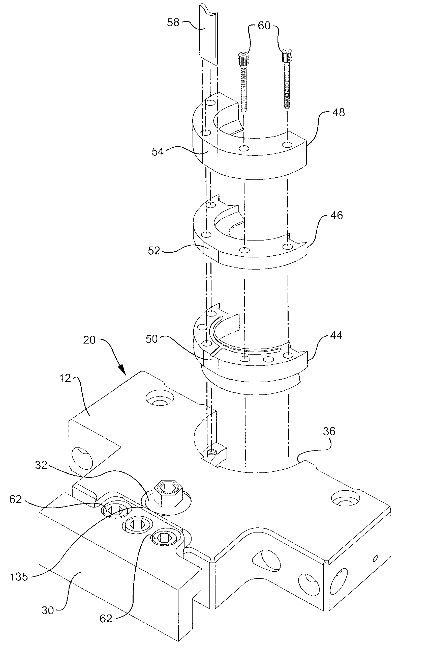
[0055]the invention is shown in FIGS. 12–14. It is similar to the embodiment of FIGS. 1–7 except that a single shim 135 is employed and the cam 32 only engages the heel 30 during the relatively “rough” adjustment of the top block half with respect to the main mold half. The same reference numerals are accordingly employed to designate elements found in FIGS. 1–7.

first embodiment

[0056]As in the first embodiment, the cam 32 is rotated to cause the heel 30 to move towards the back plate. Because the cam has flat surfaces 33, the heel moves in discrete increments with respect to the top block half. Once the tonnage pad sections are aligned with the face of the main mold half and the heel engages the back plate 14, the space between the tail face of the top block half and the front face of the heel can be measured. The cam 32 can then be rotated out of engagement with the heel 30 and an appropriate shim 135 moved into the space between the top block half and heel. The cam can also engage the shim 135 as shown in FIGS. 13–14, though such engagement is not essential.

[0057]The flat surfaces 33 of the cam are preferably equal in size such that the heel moves in equal increments as the cam is rotated. Each increment can correspond to a shim of selected thickness. One servicing the mold accordingly can determine which size shim to choose based on the number of discre...


PUM

PropertyMeasurementUnit
Thicknessaaaaaaaaaa
Depthaaaaaaaaaa

Abstract

A top block assembly for a container blow mold system is provided together with a method of positioning the neck finish components of the assembly with respect to the front face of a top block half. A method and assembly for positioning a top block half with respect to a main mold half is further provided. The assembly for positioning the neck finish components includes a feeler gauge or spacer that is removably positioned between the top block half and the rear surfaces of the neck finish components. The positions of the neck finish components with respect to the front face of the top block half are adjusted by positioning a feeler gauge between the top block half and neck finish components. A heel is movably mounted to the top block half. A cam having flat surfaces is rotatably mounted to the top block half and engageable with the heel.

Description

CROSS REFERENCE TO RELATED APPLICATIONS[0001]This application claims the priority of U.S. provisional application Ser. No. 60 / 354,558 filed Feb. 5, 2002 and U.S. provisional application 60 / 368,513 filed Mar. 29, 2002.FIELD OF THE INVENTION[0002]This invention relates to a top block assembly for a container blow-mold system which facilitates proper alignment of components such as the top block half, master seal, shear steel and neck finish insert, and a method of positioning such components.BACKGROUND OF THE INVENTION[0003]The blow molding of plastic containers is well known and practiced worldwide. Blow-molding offers many advantages over other forms of container manufacturing.[0004]Among these advantages are: the ability to produce containers at minimal cost and with minimal waste; the low start-up costs and mold making lead times in comparison to other manufacturing methods such as injection molding; the ability to produce irregular shaped and hollow containers; the ability to pro...

Claims


Application Information

Patent Timeline
IPC IPC(8): B29C49/48B29C49/78B29C49/06
CPCB29C49/48B29C49/78B29C49/06B29C2949/0715
Inventor WOHLGEMUTH, EMANUEL E.
Owner ULTRASEAL TECH
Why Eureka
Try Eureka