High ratio, reduced size epicyclic gear transmission for rotary wing aircraft with improved safety and noise reduction

a technology gear transmission, which is applied in the direction of gearing details, gearing, transportation and packaging, etc., can solve the problems of generating high noise levels in operation, limiting the load capacity of epicyclic gear transmission, and affecting the safety of rotary wing aircraft, so as to reduce the number of parts and simplify assembly. , the effect of reducing nois

Inactive Publication Date: 2005-11-22
THE BOEING CO
View PDF4 Cites 26 Cited by
  • Summary
  • Abstract
  • Description
  • Claims
  • Application Information

AI Technical Summary

Benefits of technology

[0010]The epicyclic gear transmission of the present invention brings together a large number of individual planetary gear system innovations which, taken together, provide improvements in noise reduction and performance of the transmission combined with improved reliability and fail safety of the transmission. The epicyclic gear transmission of the invention makes use of a compound epicyclic gear system with as many as double the number of planet gears sharing the load of the transmission without an increase in the overall diameter of the basic epicyclic gear drive. This reduces the weight of the transmission and provides the transmission with a smaller footprint. The compound epicyclic gear transmission also provides a more fail-safe, quieter gear drive for rotary wing applications.
[0011]The epicyclic gear transmission of the invention is provided in several embodiments. Each of the embodiments makes use of interleaved planet gear clusters with there being two or three planet gears on each planet gear shaft. Interleaving the planet gear clusters enables doubling of the number of planet gears in the transmission system. This increases the load capacity of the transmission (almost doubling the load capacity) without decreasing the reduction ratio obtained through the gear transmission and without increasing the diameter of the overall gear transmission. Some axial length is added to the transmission, however, this adds minimal weight and a minimal increase in size.
[0012]Using double helical planet gears that are axially staggered in their positions on their planet gear shafts enables doubling the number of planet gears in the epicyclic gear transmission. Because double helical gears require a gap at the apex of their gear teeth to permit the teeth to be ground, they are normally heavier than single helical gears. By staggering the planet gears axially on the planet gear shafts in the transmission, the apex gap between the double helical planet gears on each planet shaft becomes an axial space between the planet gears that can be occupied by an interleaving planet gear of the adjacent planet gear shaft. This enables doubling the number of planet gears that can be used at any gear ratio. Doubling the planet gears significantly increases the load capacity of the transmission. Employing double helical planet gears also results in noise reduction. Employing double helical planet gears on each planet shaft basically creates a dual path transmission system that significantly enhances the survivability and fault tolerance of the gear transmission. The usual detrimental need for providing a large apex gap on a double helical gear is turned into an advantage by providing an axial space between double helical planet gears on each planet shaft that can be occupied by an interleaving planet gear of an adjacent planet gear shaft. The axial spacing between the double helical planet gears on each planet shaft also allows easy manufacturing of the gears while minimizing the weight penalty associated with the need for the axial gap between double helical gears to allow for the cutting tool and grinding wheel runout in manufacturing the gears.

Problems solved by technology

While this basic epicyclic gear transmission provides relatively good power efficiency, it has a tendency to generate high noise levels in operation due to the limited contact ratio of the sun gear and the internal ring gear with the multiple planet gears.
In addition to the undesirable high noise levels generated by the basic epicyclic gear transmission, the load capacity of the epicyclic gear transmission is limited by it being a function of the number of planet gears that can be accommodated inside the internal ring gear.
Because the gears of the basic epicyclic gear transmission are densely packed to reduce the size of the transmission, a gear tooth failure of one of the gears can generally be very destructive.
The high power density provided by an epicyclic gear transmission and the very limited space among the gears of the transmission causes a great deal of consequential damage from a fractured tooth in the transmission.
It has been observed that the planet gears themselves provide little in the way of fail safety.
This is especially true when one considers that once a planet gear loses its load-transmitting capability, the internal load balance between the multiple planet gears is compromised so that the planet gears no longer balance their own radial loads on the sun gear and the internal ring gear.

Method used


Image

  • High ratio, reduced size epicyclic gear transmission for rotary wing aircraft with improved safety and noise reduction
  • High ratio, reduced size epicyclic gear transmission for rotary wing aircraft with improved safety and noise reduction
  • High ratio, reduced size epicyclic gear transmission for rotary wing aircraft with improved safety and noise reduction

Examples


first embodiment

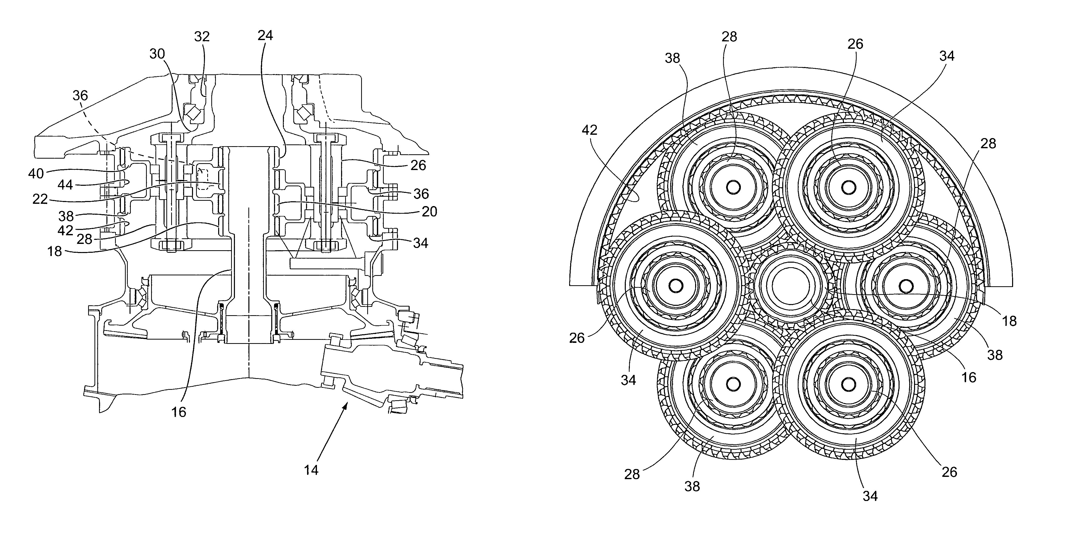
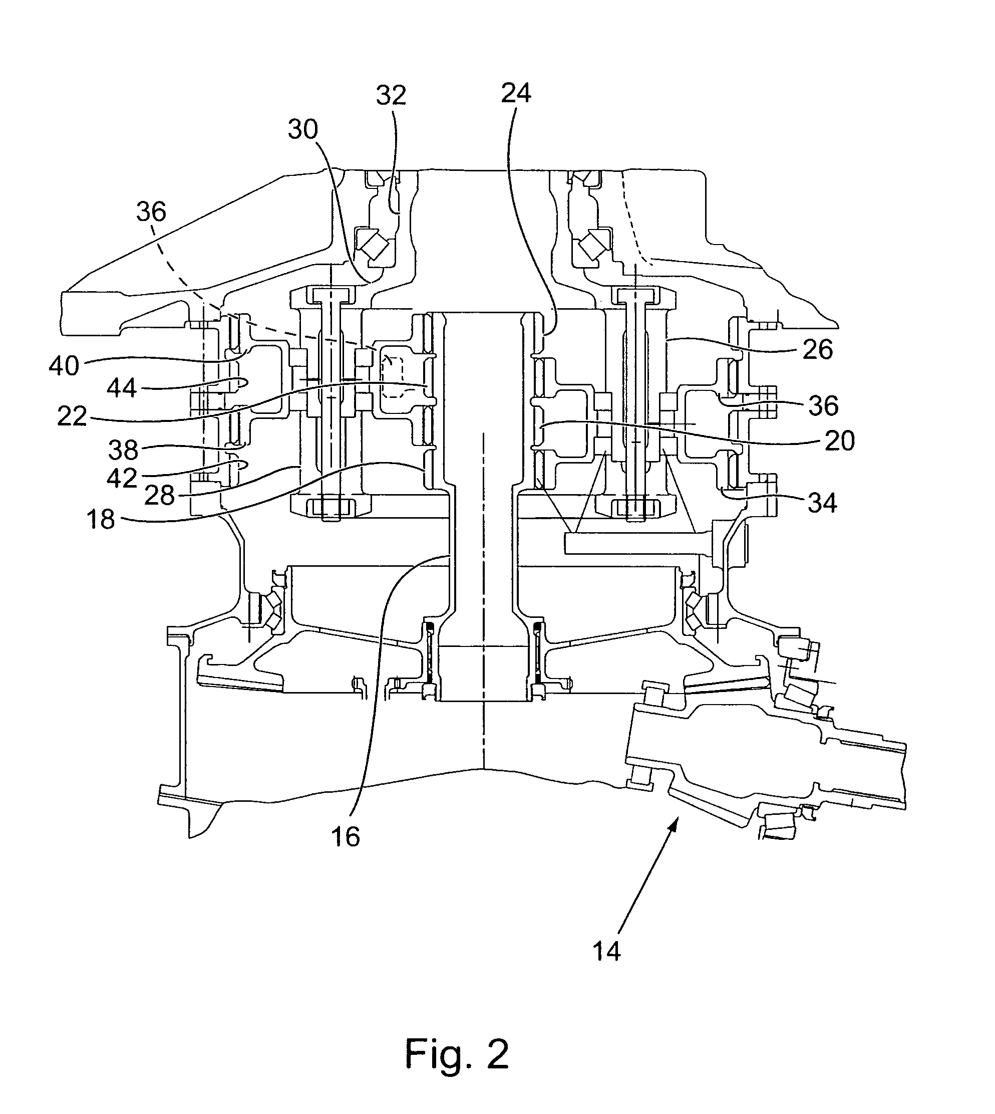
[0035]FIGS. 2–5 show the epicyclic gear transmission of the present invention. The input drive of the transmission is from a motive source 14 of the aircraft that drives an input shaft 16 having a center axis that is also the center axis of the transmission. A sun gear cluster comprised of four sun gears 18, 20, 22, 24 is provided on the input shaft 16. The four sun gears are axially arranged in two pairs. A first pair of the sun gears 18, 22 are double helical gears having opposite hand gear teeth of equal helix angles. The second pair of the sun gears 20, 24 are also double helical gears with opposite hand gear teeth with the same helix angles as the first pair of sun gears.

[0036]Each of the sun gears 18, 20, 22, 24 meshes with clusters of planet gears mounted on planet gear shafts 26, 28 of a planet gear carrier 30. The planet gear shafts 26, 28 have center axes that are parallel with the center axis of the input shaft 16. The planet gear carrier 30 is formed integrally with an o...

fourth embodiment

[0050]the epicyclic gear transmission is basically the same as that shown in FIGS. 6–9 except that high-profile contact ratio (HCR) spur gears are used as the sun gears 54, 56 and the planet gears 68, 74 that mesh with the sun gears. This configuration of the epicyclic gear transmission simplifies assembly and allows the double helical planet gears 70, 72, 76, 78 that mesh with the ring gears 80, 82 to be true double helical gears having equal helix angles of opposite hands. This configuration eliminates any axial thrust loads on the stationary internal ring gears 80, 82. The HCR gears also provide noise reduction without the additional thrust load that results from helical gears.

[0051]The use of the double helical planet gears on each planet gear shaft that mesh with the internal ring gears of the embodiments of the transmissions described improves the safety of each of the embodiments of the epicyclic gearing transmission. The double helical gears meshing with the internal ring ge...


PUM


Abstract

A high ratio, double helical epicyclic gear transmission that is primarily intended for use in rotary wing aircraft employs double helical planet gears to obtain a reduction in size of the transmission, to improve the safety of the transmission, and to reduce the noise created by operation of the transmission.

Description

[0001]The invention was developed in the course of work done under U.S. government contract NCC2-9019. The U.S. government may possess certain rights in the invention.BACKGROUND OF THE INVENTION[0002](1) Field of the Invention[0003]The present invention pertains to an epicyclic gear transmission that is primarily intended for use in rotary wing aircraft, i.e., helicopters. More specifically, the present invention pertains to a high ratio, double helical epicyclic gear transmission that employs double helical planet gears to obtain a reduction in size of the transmission, to improve the safety of the transmission, and to reduce the noise created by the operation of the transmission.[0004](2) Description of the Related Art[0005]In rotary wing aircraft, the main rotor gear transmission is the most critical and usually the heaviest single subsystem in the drive system of the aircraft. This is true for a single or tandem rotor helicopter, or a tilt rotor aircraft.[0006]Currently, the fin...

Claims


Application Information

Patent Timeline
Patent Type & Authority Patents(United States)
IPC IPC(8): B64C27/00B64C27/12F16H1/46F16H1/28F16H57/00F16H57/08
CPCB64C27/12F16H1/28F16H1/46F16H57/082
Inventor DRAGO, RAYMOND J.LENSKI JR., JOSEPH W.ROBUCK, MARK J.
Owner THE BOEING CO
Why Eureka
Try Eureka