Architectural preset rotary and preset slide control and non-preset controls

a technology of architectural preset rotary and slide control, applied in contact mechanisms, instruments, printing, etc., can solve the problems of difficult operator manipulation of switching actuators, complicated design of such switches, and difficult control of switches, etc., and achieve the effect of easy assembly

Active Publication Date: 2005-11-22
LEVITON MFG
View PDF9 Cites 12 Cited by
  • Summary
  • Abstract
  • Description
  • Claims
  • Application Information

AI Technical Summary

Benefits of technology

[0006]The present invention provides an architectural preset rotary and slide control device that is used to route electrical energy to devices and / or systems and to control the amount of electrical energy routed to the electrical devices and / or systems. The device of the present invention has a modular design which facilitates assembly of such device during its manufacture. The device of the present invention comprises an N-mode latch that is mechanically coupled to a switch whereby the operation of the latch causes the device to route electrical energy through the switch to one of a plurality of electrical devices and / or systems each of which is electrically coupled to a terminal of the switch. The device further comprises a variable control component electrically coupled to the switch and other electrical components such that when this component is operated it controls the amount of electrical energy that is routed through the switch of the device of the present invention. In a preferred embodiment, the latch is configured so as to enter one of N modes each time it is activated; N is an integer equal to 2 or greater.
[0008]The switch has a plurality of modes each corresponding to a particular preset position of the switch actuator which corresponds to the electrical coupling of the pole to one of a plurality of receiving terminals. In other words, each time the latch is activated, it engages the switch at a different preset position thereby causing the switch to electrically couple its pole to one of a plurality of receiving terminals thereby routing electrical energy or electrical signals at the pole to one of a plurality of receiving terminals. The variable control component is configured as a rotary control or slide control potentiometer electrically coupled to the switch along with other electrical components to control the amount of energy that is routed through the switch.
[0009]The design of the device of the present invention is modular in that many of the various components are implemented as single piece components or modules that can be easily assembled during the manufacture of the device. In particular, the latch is a one-piece component that mates with a one-piece latch lock spring retainer. Further, the switch is a one-piece electromechanical part with terminals one of which is a pole ant the others are receiving terminals. The device of the present invention also has a one-piece housing or in another embodiment a two-piece housing arrangement where the housing components mate with each other. The variable control component is also a one-piece device. As with most modular designs, many of the components are interchangeable with other similar components thus allowing the device of the present invention to be constructed in a variety of arrangements.

Problems solved by technology

The design of such switches is often complicated by the need to route electrical energy to devices or systems while at the same controlling the amount of energy being provided to these devices or systems.
Consequently, these switches often have very awkward control and switching actuators that are difficult to manipulate by an operator.
Further, the assembly of these switches during manufacture is also difficult because of the relatively small size of the switch electrical and mechanical components and the intricate interconnections that often exist between these various components.

Method used


Image

  • Architectural preset rotary and preset slide control and non-preset controls
  • Architectural preset rotary and preset slide control and non-preset controls
  • Architectural preset rotary and preset slide control and non-preset controls

Examples


Embodiment Construction

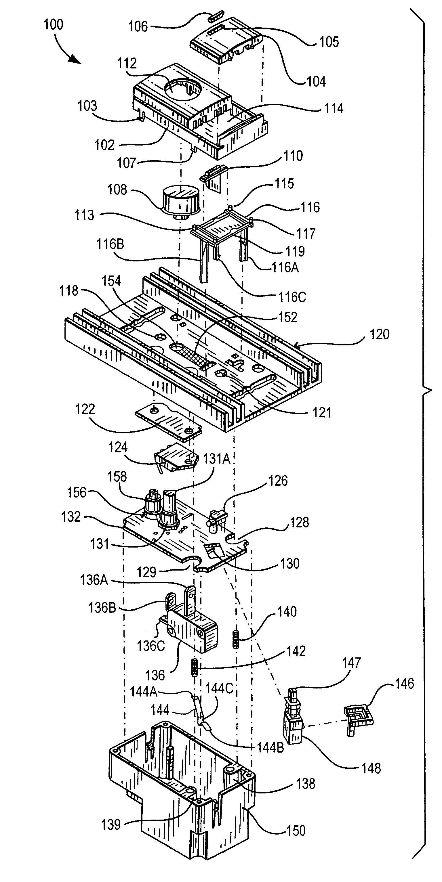
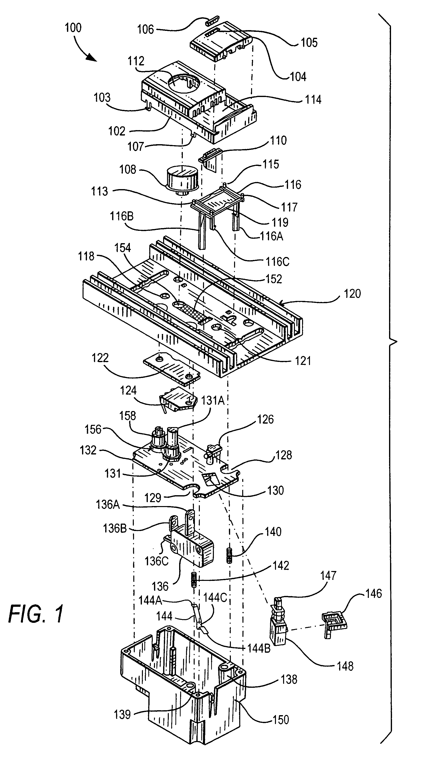
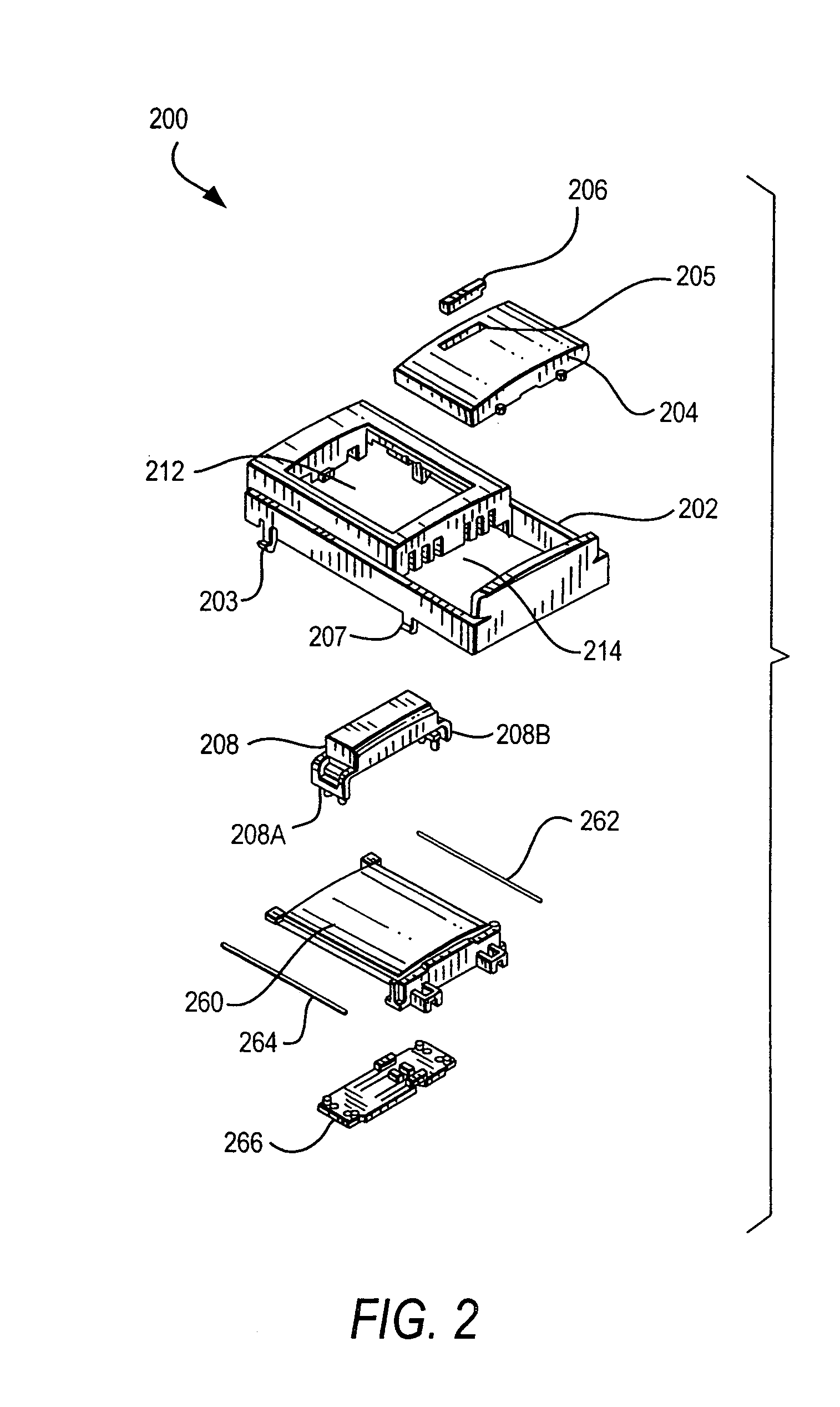
[0013]The present invention provides an architectural preset rotary and slide control device that is used to route electrical energy to devices and / or systems and to control the amount of electrical energy routed to the electrical devices and / or systems. The device of the present invention has a modular design which facilitates assembly of such device during its manufacture. The device of the present invention comprises an N-mode latch that is mechanically coupled to a switch whereby the operation of the latch causes the device to route electrical energy through the switch to one of a plurality of electrical devices and / or systems each of which is electrically coupled to a terminal of the switch. The device further comprises a variable control component electrically coupled to the switch and other electrical components such that when this component is operated it controls the amount of electrical energy that is routed through the switch of the device of the present invention. In a p...


PUM


Abstract

An architectural preset rotary and preset slide control device comprising an N-mode latch mechanically coupled to a switch having a pole and a plurality of receiving terminals. The device further comprises a variable control component that is electrically coupled to the switch such that when the latch is activated into one of the N modes, the switch pole is caused to be electrically coupled to one of the receiving terminals allowing electrical energy at the pole to be routed through the switch to one of the receiving terminals. The variable control component controls the amount of electrical energy that is routed through the switch. The device has a modular design in that the switch, latch, variable control component and other parts of the device are single piece parts that facilitate the assembly of the device during its manufacture.

Description

BACKGROUND OF THE INVENTION[0001]1. Field of the Invention[0002]The present invention generally relates to electromechanical rotary and slide control switches.[0003]2. Description of the Related Art[0004]Electromechanical switches for controlling electrical devices and / or systems such as lighting systems typically comprise many electrical components and mechanical components that are electrically and / or mechanically coupled to each other. Depending on the particular application, the systems and / or devices that are controlled by the switches often require multiple simultaneous application and control of electrical energy in the form of electrical current or voltage. The application of electrical energy is typically implemented with a switch that electrically connects or disconnects the electrical device or system to or from a source of electrical energy. The control of electrical energy is typically implemented with a variable control arrangement such as a variable potentiometer that...

Claims


Application Information

Patent Timeline
Patent Type & Authority Patents(United States)
IPC IPC(8): G03B27/32H01H15/00H01H19/00H01H17/00H01H17/02H01H3/02H01C10/50H01H9/52
CPCH01C10/50H01H3/0213H01H9/52
Inventor KRAJCI, EDWARD J.MEINERS, FRED R.KHLEB, MICHAEL
Owner LEVITON MFG
Why Eureka
Try Eureka