
Error-correction apparatus for step-motor transmission system and a method for the same

a transmission system and error correction technology, applied in the direction of dynamo-electric converter control, programme control, instruments, etc., can solve the problems of time-consuming post-correction, high-end step motor b>10/b> is generally expensive, and the transmission system of the same still has a certain amount of errors, etc., to enhance the operation and enhance the correctness of the step motor.

Inactive Publication Date: 2005-11-22
SERVICE & QUALITY TECHNOLOGY CO LTD
View PDF5 Cites 4 Cited by
  • Summary
  • Abstract
  • Description
  • Claims
  • Application Information

AI Technical Summary

Benefits of technology

[0008]It is the object of the present invention to provide an error-correction apparatus for a step motor transmission system and a method for the same, in which a rotational error gamma table is provided for an ordinary step motor and the error-correction apparatus produces a compensated driving current with reference to the a rotational error gamma table to enhance operation. The compensated driving current drives the coils of the step motor to enhance operational correctness of the step motor.

Problems solved by technology

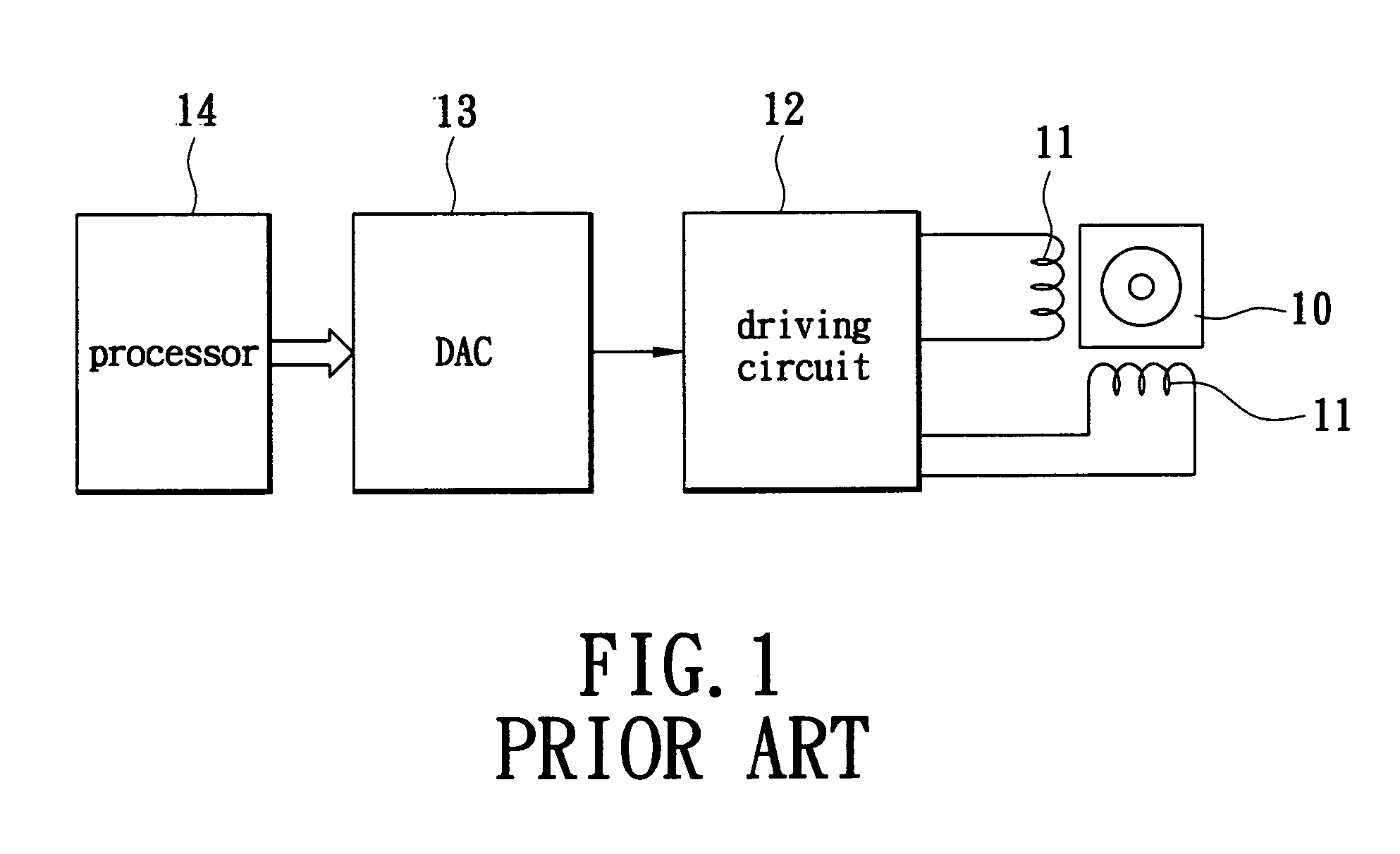
However, the high-end step motor 10 generally is expensive and the transmission system thereof still has a certain amount of error, which results from fabrication error in the f inductor coil 11.
A time-consuming post-correction is thus needed.

Method used


Image

  • Error-correction apparatus for step-motor transmission system and a method for the same
  • Error-correction apparatus for step-motor transmission system and a method for the same
  • Error-correction apparatus for step-motor transmission system and a method for the same

Examples


Embodiment Construction

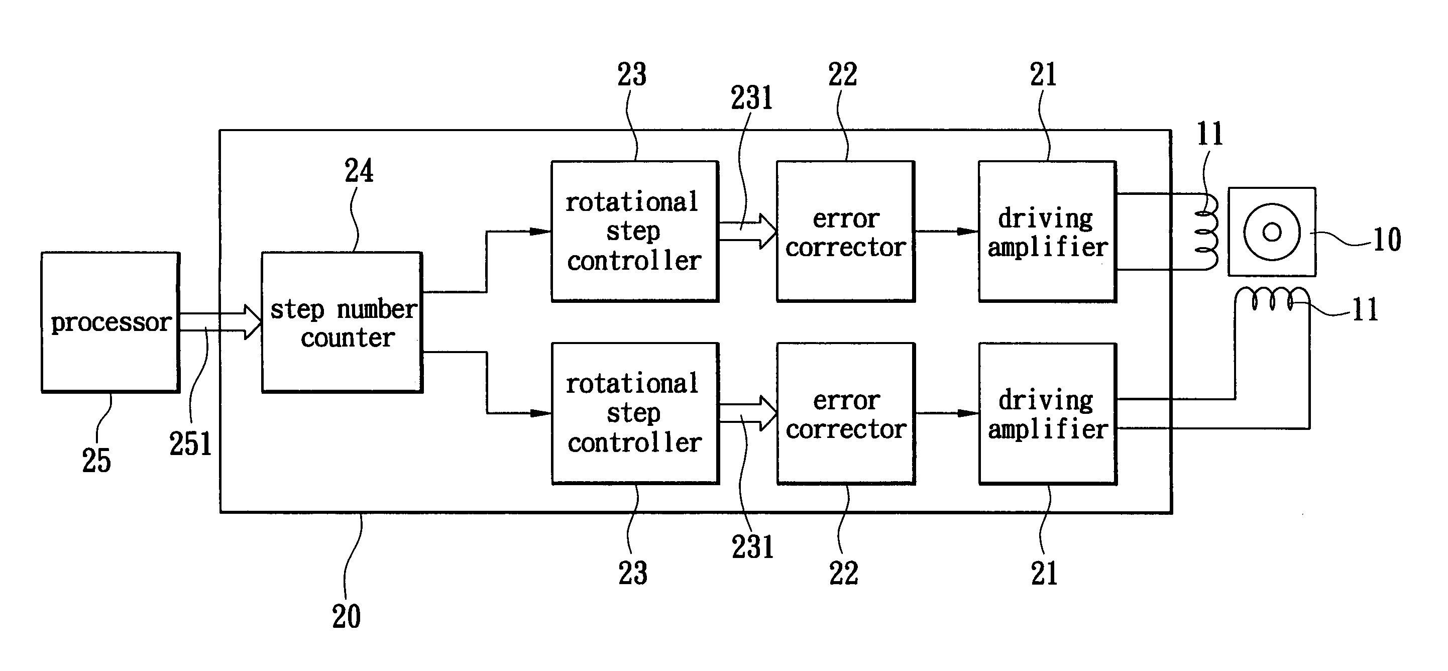
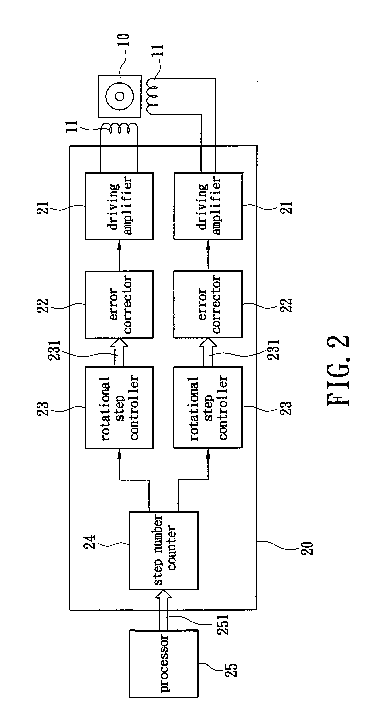
[0017]FIG. 2 shows a schematic diagram of the error-correction apparatus for a step motor 10, in which the step motor 10 is exemplified with 2-phase step motor providing 8 steps per revolution. A high-end step motor provides more than 200 steps per revolution. It should be noted that the error-correction apparatus of the present invention could also be applied to a high-end step motor.

[0018]In the present invention, an error-correction apparatus 20 is arranged on the step motor 10. In this preferred embodiment, the step motor 10 comprises two sets of inductor coils 11 for controlling a step number of an internal shaft (not shown) of the step motor 10. The error-correction apparatus 20 comprises two sets of driving amplifiers 21, two sets of error correctors 22, two sets of rotational step controllers 23 and a step number counter 24, and receives a digital displacement signal 251 from a processor 25.

[0019]The driving amplifiers 21 are electrically connected to the two inductor coils ...


PUM


Abstract

An error-correction method and apparatus are used for a step motor transmission system. The step motor has a plurality of inductor coils therein for rotating an internal shaft thereof. A rotational error gamma table is established by measuring an error value for each rotational step of the step motor. The error-correction apparatus receives an external digital displacement signal for producing a rotational step signal. A compensation current is produced according to the rotational step signal and an error value in the rotational error gamma table. The inductor coils are driven by the compensation current to rotate the internal shaft precisely.

Description

BACKGROUND OF THE INVENTION[0001]1. Field of the Invention[0002]The present invention relates to an error-correction apparatus for a step motor transmission system and a method for the same, and especially to an error-correction apparatus for correcting step error in a step motor-transmission system and a method for the same.[0003]2. Description of Prior Art[0004]The digital electronic products are prevalent in modern ordinary life. Among them, the high-end digital still camera and scanner have been developed to use a step motor to enhance image quality. More particularly, the transmission system of a step motor is under intense research to provide precise control.[0005]The step motor comprises a plurality of precise inductor coils to control precise rotation of internal shaft in the step motor. Therefore, the step motor can provide precise moving displacement. Taking a high-end scanner as an example, the image quality thereof depends not only on a CMOS sensor thereof but also on th...

Claims


Application Information

Patent Timeline
Patent Type & Authority Patents(United States)
IPC IPC(8): H02P8/12H02P8/22
CPCH02P8/22
Inventor TSENG, CHING-TUNG
Owner SERVICE & QUALITY TECHNOLOGY CO LTD
Learn More