
Method and apparatus for monitoring transmission quality

a transmission quality and transmission method technology, applied in the field of wireless communications networks, can solve the problems of no ideal method of monitoring transmission quality in wireless communications systems, system operation and performance cannot be maintained without, and achieve the effect of monitoring transmission quality and improving channel throughpu

Inactive Publication Date: 2005-11-22
QUALCOMM INC
View PDF11 Cites 25 Cited by
  • Summary
  • Abstract
  • Description
  • Claims
  • Application Information

AI Technical Summary

Benefits of technology

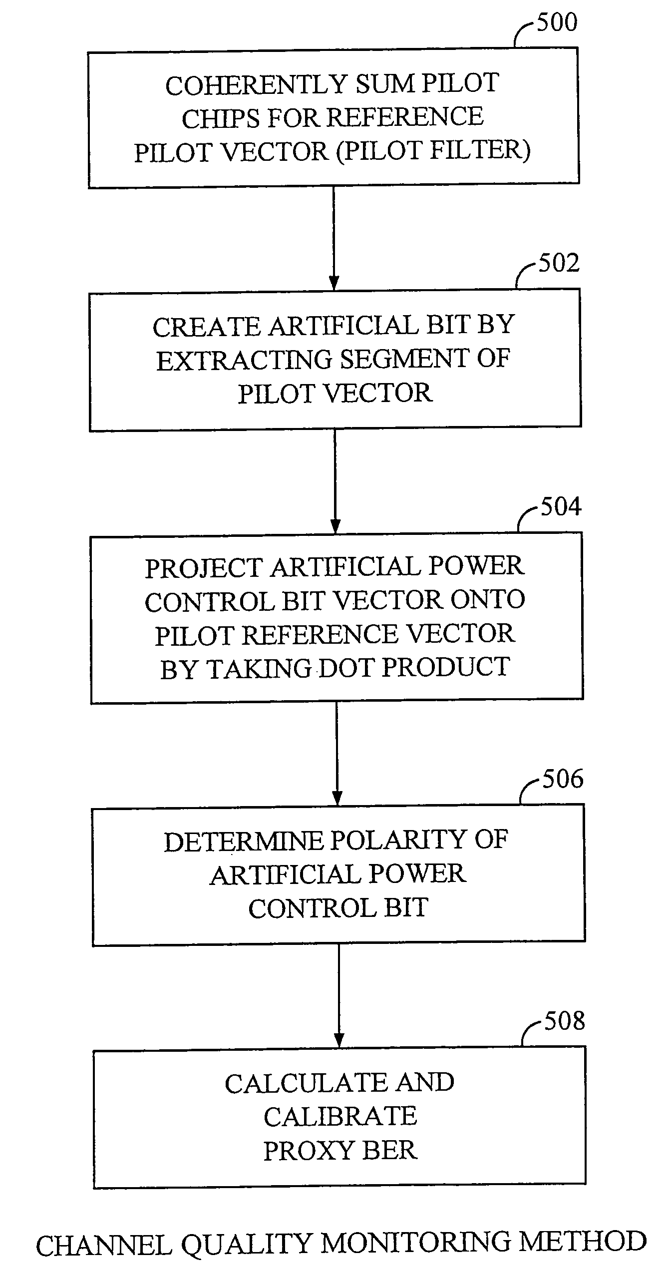
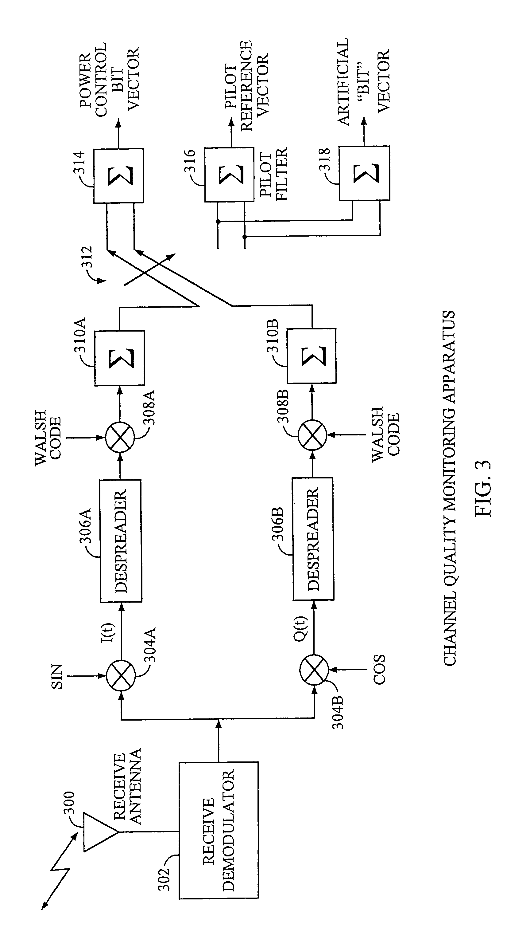
[0008]The present invention is a novel and improved method of monitoring wireless communication transmission channel quality without using a percentage of the channel throughput, energy, and time previously used for insertion of monitoring information. The method of the present invention improves channel throughput and provides a closer measure of actual BERs by reusing information already carried in the channel for other purposes. By taking advantage of known information, such as pilot symbols, to calculate BERs, the present invention can monitor transmission quality without utilizing channel bandwidth for this purpose.

Problems solved by technology

System operation and performance cannot be maintained without accurate real time transmission quality feedback information.
Presently, there is no ideal method of monitoring transmission quality in wireless communications systems.
Additionally, CRCs only indicate the presence of block errors, not a true measure of the BER.

Method used


Image

  • Method and apparatus for monitoring transmission quality
  • Method and apparatus for monitoring transmission quality
  • Method and apparatus for monitoring transmission quality

Examples


Embodiment Construction

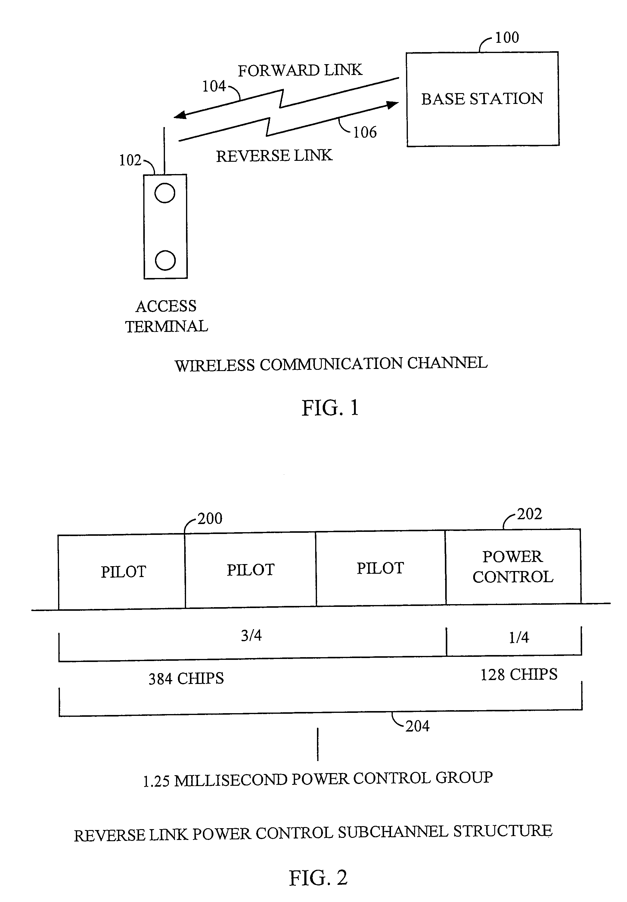
[0017]FIG. 1 shows a high level diagram of a wireless communications link between Base Station 100 and Access Terminal 102. Access Terminals 102 are also known as mobile stations in wireless communications systems. Base Station 100 and Access Terminal 102 communicate over 2 links known as Forward Link 104 and Reverse Link 106. Information travels from Base Station 100 to Access Terminal 102 over Forward Link 104. Access Terminal 102 is the receiver in the Forward Link 104. Information travels from Access Terminal 102 to Base Station 100 over Reverse Link 106. Base Station 100 is the receiver in the Reverse Link 106.

[0018]In the IS2000 system, reverse Link 106 has 4 channels; the Reverse Fundamental Channel, the Reverse Dedicated Control Channel, the reverse pilot channel, and the Reverse Supplemental Channel. A reverse power control sub-channel is punctured into the reverse pilot channel, prior to Walsh channelization and PN spreading. Bits are punctured in with a value of +1 or −1....


PUM


Abstract

In wireless communications, it is necessary to monitor the transmission quality of communications channels to maintain system performance and operation. The invention provides a way of measuring bit error rates in channels at the receiver, without diminishing channel throughput by inserting quality monitoring data into the signal at the transmitter.

Description

BACKGROUND OF THE INVENTION[0001]I. Field of the Invention[0002]The current invention relates to wireless communications networks. More particularly, the present invention relates to a novel and improved method of monitoring the transmission quality of wireless communications channels.[0003]II. Description of the Related Art[0004]Monitoring the transmission quality of communication channels in wireless communications networks is necessary for system operation. System operation and performance cannot be maintained without accurate real time transmission quality feedback information.[0005]Transmission quality is measured in terms of Bit Error Rate (BER). In telecommunication transmissions, the bit error rate is the percentage of bits that have errors relative to the total number of bits received in a transmission. The BER is usually expressed as a percentage. For example, a transmission might have a BER of 4%, meaning that, out of 100 bits transmitted, 4 bits were received in error.[0...

Claims


Application Information

Patent Timeline
IPC IPC(8): H04Q7/38H04B7/26H04B17/00H04W28/04
CPCH04B17/327H04B17/309H04W28/04
Inventor CHEN, TAOLING, FUYUNTIEDEMANN, JR., EDWARD G.
Owner QUALCOMM INC
Learn More