

Cylinder lock
- Summary
- Abstract
- Description
- Claims
- Application Information
AI Technical Summary
Benefits of technology
Problems solved by technology
Method used
Image

Examples
first embodiment
[0111]Even when the key insertion hole 15c of each of the key-driven tumblers 15 is in the state as shown, i.e., at a position shifted with respect to the key plate insertion axis c1 by an engagement allowance distance of the ride-over projections 26d, the key insertion hole 15c has a width (w) enough to receive the key plate 1. Hence, the rotor 3 can be rotated whatever kind of the code forming portion 1a is formed in the key plate 1, as in the
[0112]In this embodiment, as shown in FIG. 13A, introductory inclination surfaces formed at the terminal end of the key plate 1 is used as the identification portion 5. When the key plate 1 with the identification portion 5 is inserted into the rotor 3, the key-driven tumblers 15 are moved to positions corresponding to the depths of the code forming groove 1a of the key plate 1 and kept there by the recovery force of the tumbler springs 27. By inserting the key plate 1 to the insertion stroke end, the introductory inclined surface 5 of the ke...
third embodiment
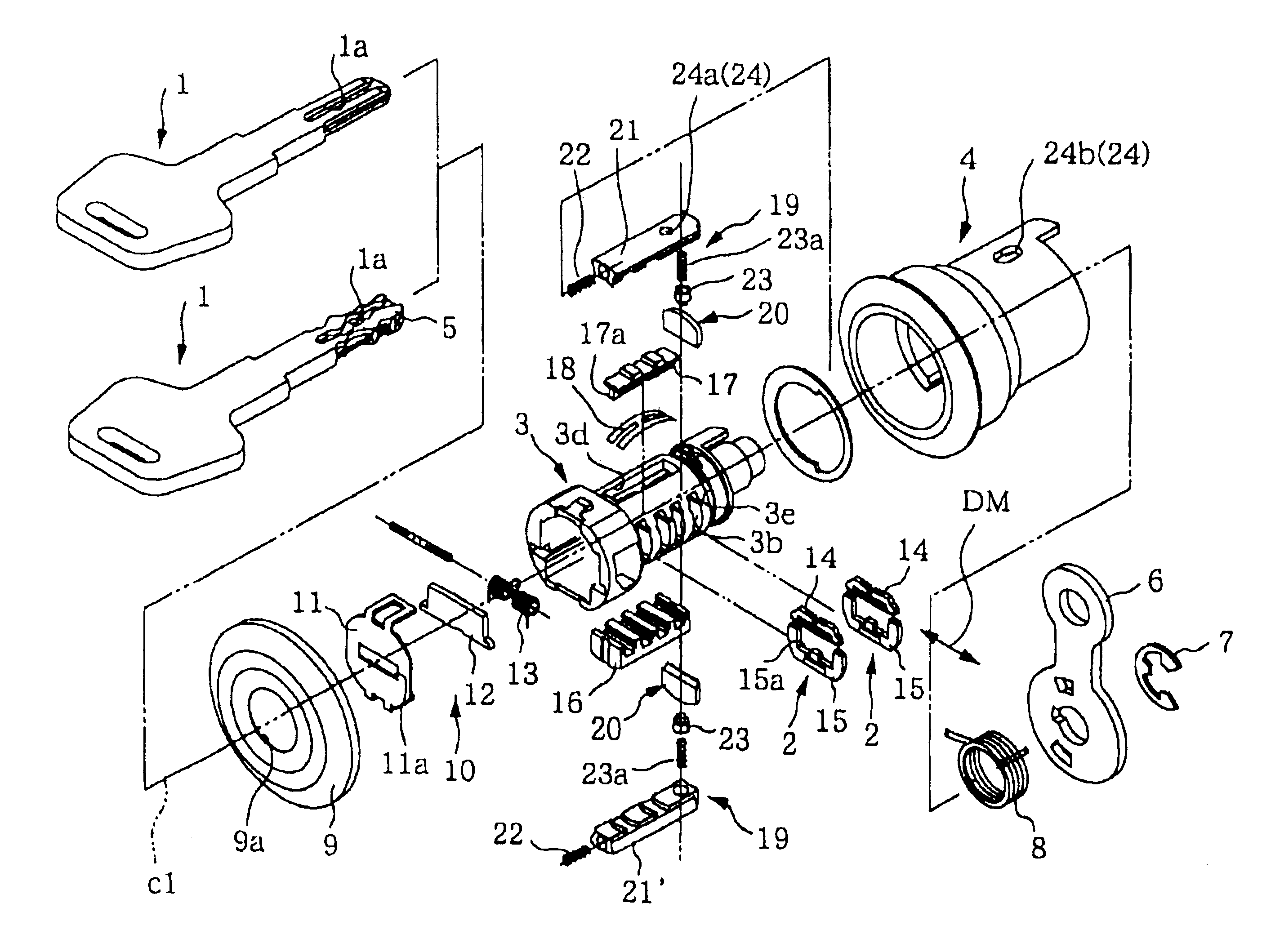
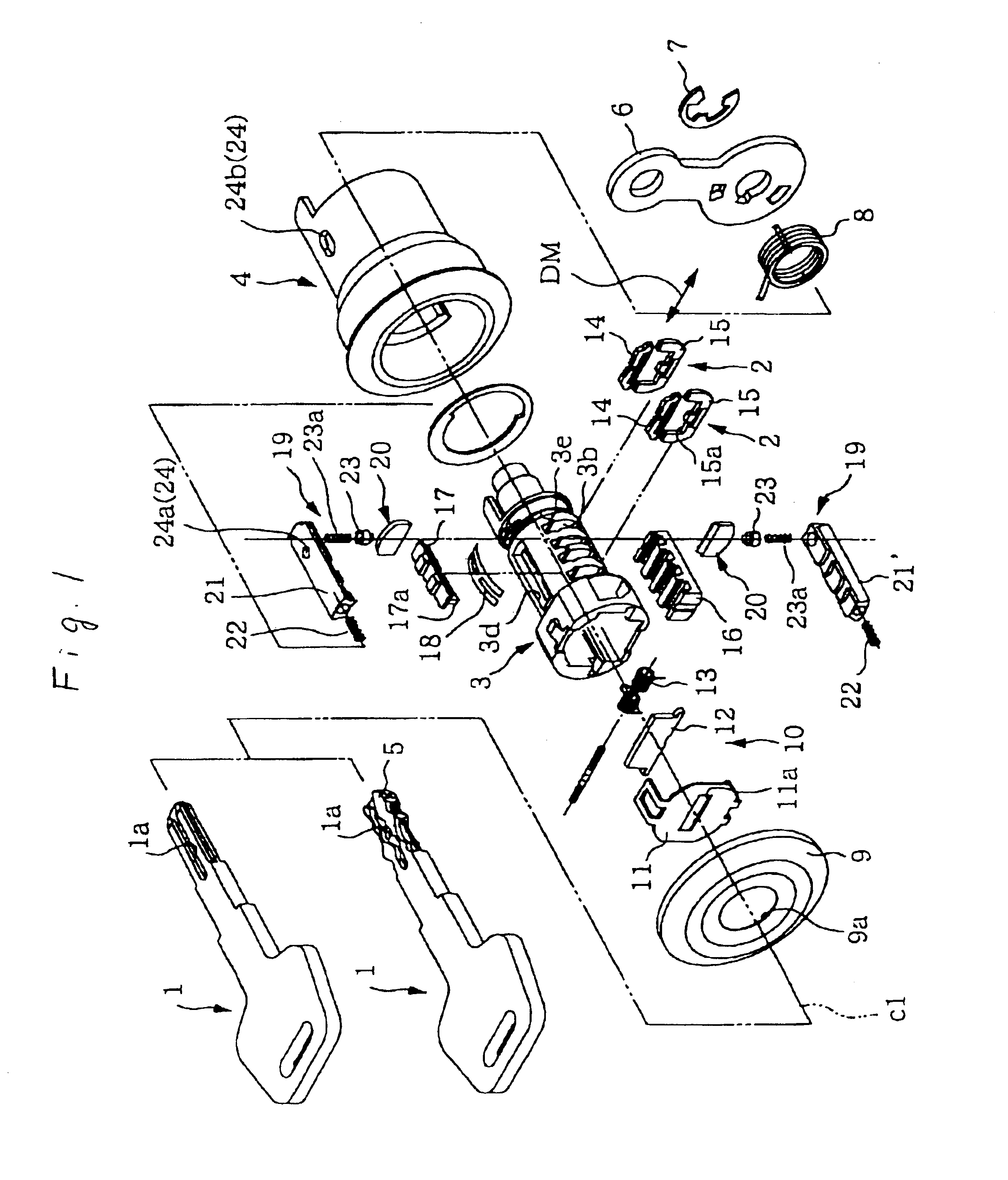
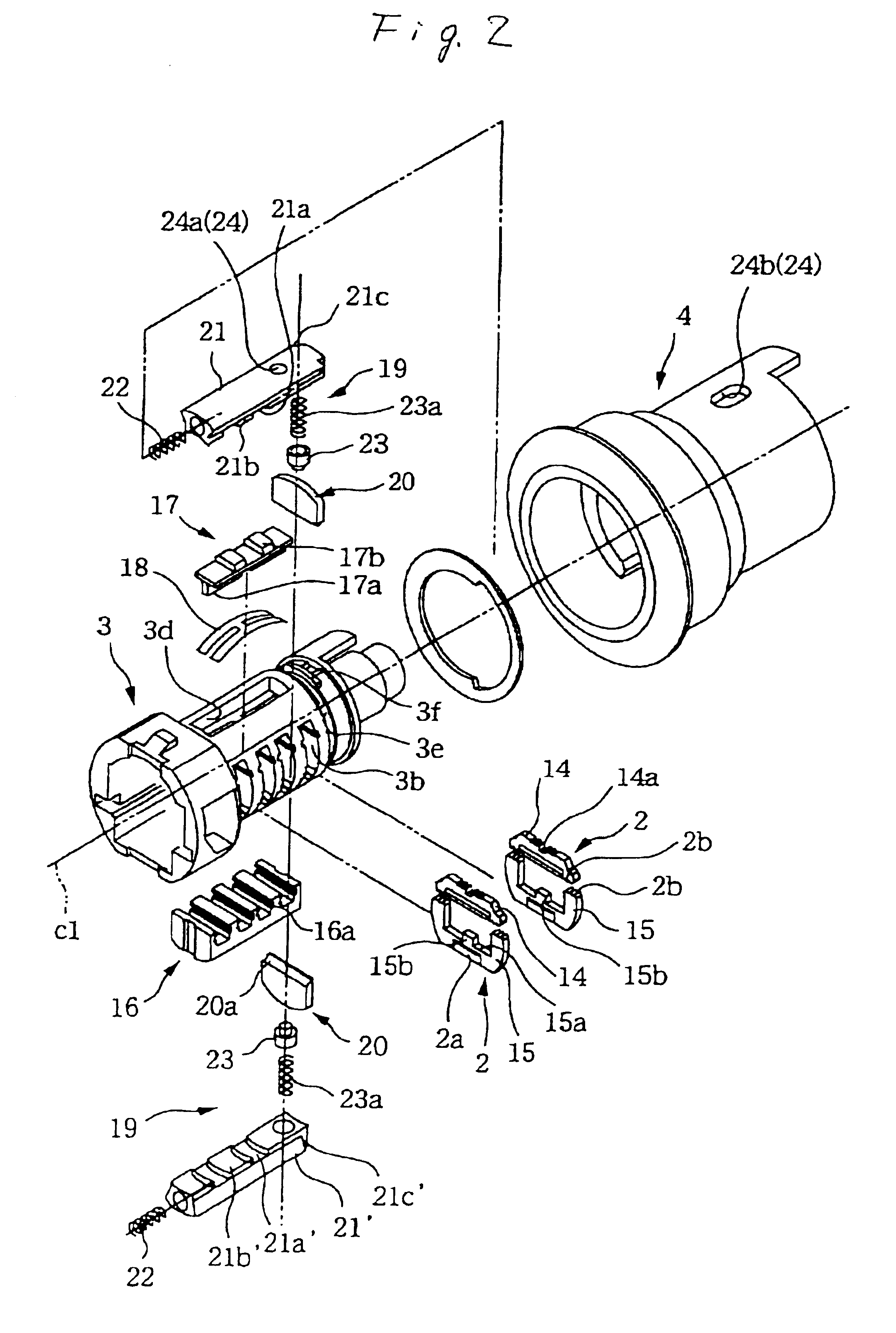
[0119]this invention is shown in FIGS. 17A to 20. In this embodiment, the key-driven tumblers 15 each have a U-shaped insertion recess 15a and are movably installed in the rotor 3 and urged by a tumbler spring 27 to move out of the rotor 3. The lock tumblers 14 installed in the rotor 3 each have a V-shaped unlock enable notch 14a with a pair of opposing inclined sides 14c, 14c and are guided in a direction perpendicular to the main moving direction (DM).
[0120]The side bar 17 has a V-shaped raised stopper strip 17a at one edge that can engage the inclined sides 14c of the unlock enable notches 14a. The side bar 17 is held in a code setting body 21 that is movable in a longitudinal direction of the cylinder case 4, the side bar 17 can be moved in a direction perpendicular to the main moving direction (DM). A bar drive spring 30 made from a compression spring is interposed between the side bar 17 and the code setting body 21, and the side bar drive spring 30 urges the side bar 17 towar...
PUM
 Abstract
Description
Claims
Application Information