Restricted flow hands-free faucet

a technology of restricted flow and faucet, applied in the direction of fluid pressure control, process and machine control, instruments, etc., can solve the problems of inadvertent activation of water flow, inability to guarantee mechanical reliability, and inability to control the flow of water in a controlled manner

Active Publication Date: 2005-11-29
DELTA FAUCET COMPANY
View PDF77 Cites 98 Cited by
  • Summary
  • Abstract
  • Description
  • Claims
  • Application Information

AI Technical Summary

Benefits of technology

[0012]In a second embodiment, a faucet according to the present invention comprises: a spout; a passageway; an electrically operable valve; a bypass; a manual valve; a manual handle; a touch-control; a proximity sensor; and a logical control. The passageway conducts water flow through the spout. The electrically operable valve is disposed within the passageway, and has an opened position, in which water is free to flow through the passageway, and a closed position, in which the passageway is blocked. The bypass has a first end above the electrically operable valve, relative to the water flow, and a second end below the electrically operable valve, such that a portion of the water flow bypasses the electrically operable valve. The manual valve is disposed within the passageway in series with the electrically operable valve. The manual handle controls the manual valve. The touch-control generates a first output signal while the touch-control is in contact with a user. The proximity sensor generates a second output signal when an object is detected within a detection zone of the proximity sensor. The logical control toggles the electrically operable valve in response to either of the first output signal and the second output signal.
[0013]In a third embodiment, a faucet according to the present invention comprises: a spout; a passageway; an electrically operable valve; and a sensor. The passageway conducts water flow through the spout. The electrically operable valve is disposed within the passageway, and has at least an open position and a closed position. The electrically operable valve makes an incomplete seal with the passageway in the closed position. The sensor is operably connected to the electrically operable valve via a logical control, the logical control generating a control signal when the sensor observes an activation event. The electrically operable valve actuates in response to the control signal.
[0014]In a fourth embodiment, a faucet according to the present invention comprises: a spout; a passageway; an electrically operable valve; a bypass; and a sensor. The passageway conducts water flow through the spout. The electrically operable valve is disposed within the passageway, and has at least an open position and a closed position. The bypass has a first end above the electrically operable valve, relative to the water flow, and a second end below the electrically operable valve, such that a portion of the water flow bypasses the electrically operable valve. The sensor is operably connected to the electrically operable valve via a logical control, the logical control generating a control signal when the sensor observes an activation event. The electrically operable valve actuates in response to the control signal.

Problems solved by technology

The former were unsatisfactory because a user could only wash one hand at a time, while the latter proved to be mechanically unreliable.
With an automatic faucet, however, the absence of a water stream does not indicate whether the faucet has been manually closed, or whether the electrically operable valve is closed and the manual valve is open.
This uncertainty can have several undesirable effects.
For example, it can result in inadvertent activation of water flow, as one may approach or put items in the sink area for certain activities when water flow is not desired.
This can be especially problematic with faucets that have a proximity sensor, since water flow can be initiated when the user places a hand or other object in the path of the proximity sensor.
Most of these problems can be especially problematic for users unfamiliar with the automatic faucet's operation, such as visitors, or even new adopters.

Method used


Image

  • Restricted flow hands-free faucet
  • Restricted flow hands-free faucet
  • Restricted flow hands-free faucet

Examples


Embodiment Construction

[0019]For the purposes of promoting an understanding of the principles of the invention, reference will now be made to the preferred embodiment and specific language will be used to describe the same. It will nevertheless be understood that no limitation of the scope of the invention is thereby intended. Such alternations to and further modifications of the invention, and such further applications of the principles of the invention as described herein as would normally occur to one skilled in the art to which the invention pertains, are contemplated, and desired to be protected.

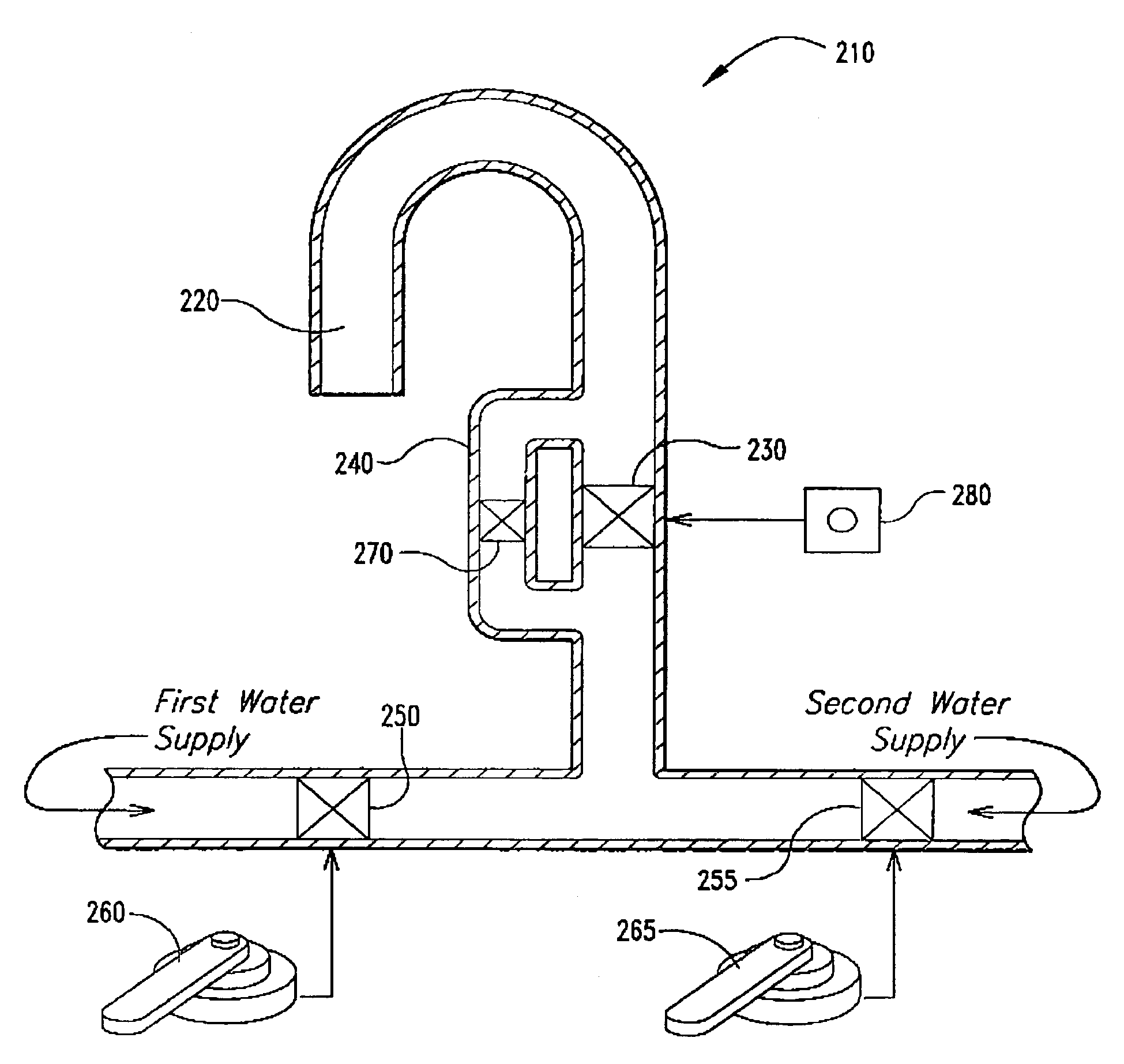
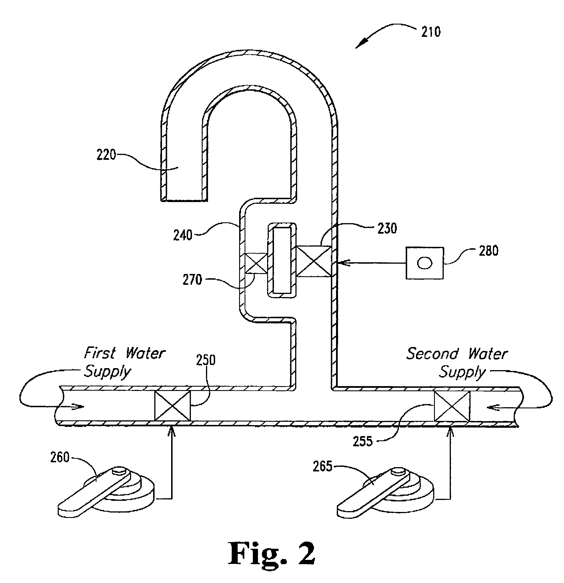
[0020]A preferred embodiment automatic faucet according to the present invention provides conspicuous and intuitively obvious visual feedback that alerts even users unfamiliar with the operation of automatic faucets when the faucet is in an automatic off state, rather than a manual off (shut down) state. In the preferred embodiment, an automatic faucet according to the present invention uses a third, restrict...


PUM


Abstract

A faucet comprising a spout, a passageway, an electrically operable valve; a first manual valve; a first manual handle; and a bypass. The passageway conducts water flow through the spout. The electrically operable valve is disposed within the passageway. The first manual valve disposed within the passageway in series with the electrically operable valve. The first manual handle that controls the first manual valve. The bypass has a first end above the electrically operable valve, relative to the water flow, and a second end below the electrically operable valve, such that a portion of the water flow bypasses the electrically operable valve.

Description

BACKGROUND[0001]1. Field of the Invention[0002]The present invention relates generally to the field of automatic faucets. More particularly, the present invention relates to an automatic faucet having a restricted flow state.[0003]2. Description of the Related Art[0004]Automatic faucets have become popular for a variety of reasons. They save water, because water can be run only when needed. For example, with a conventional sink faucet, when a user washes their hands the user tends to turn on the water and let it run continuously, rather than turning the water on to wet their hands, turning it off to lather, then turning it back on to rinse. In public bathrooms the ability to shut off the water when the user has departed can both save water and help prevent vandalism.[0005]One early version of an automatic faucet was simply a spring-controlled faucet, which returned to the “off” position either immediately, or shortly after, the handle was released. The former were unsatisfactory bec...

Claims


Application Information

Patent Timeline
Patent Type & Authority Patents(United States)
IPC IPC(8): E03C1/05F16K31/02
CPCE03C1/05Y10T137/9464Y10T137/87547Y10T137/87507Y10T137/87281Y10T137/87917
Inventor HAENLEIN, HANS-CHRISTOPHARKO, ROBERT P.TSUEI, KAREN L.
Owner DELTA FAUCET COMPANY
Why Eureka
Try Eureka