
Elevator apparatus

Inactive Publication Date: 2005-11-29
TEIJIN SEIKI CO LTD
View PDF21 Cites 4 Cited by
  • Summary
  • Abstract
  • Description
  • Claims
  • Application Information

AI Technical Summary

Benefits of technology

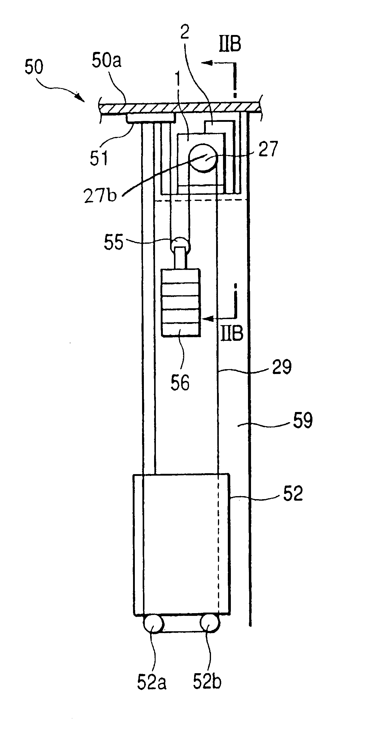
[0006]In view of the above described problems, it is an object of the invention to provide such an elevator apparatus that the cost for installing the elevator can be kept low, and that effective spaces are secured in the building.
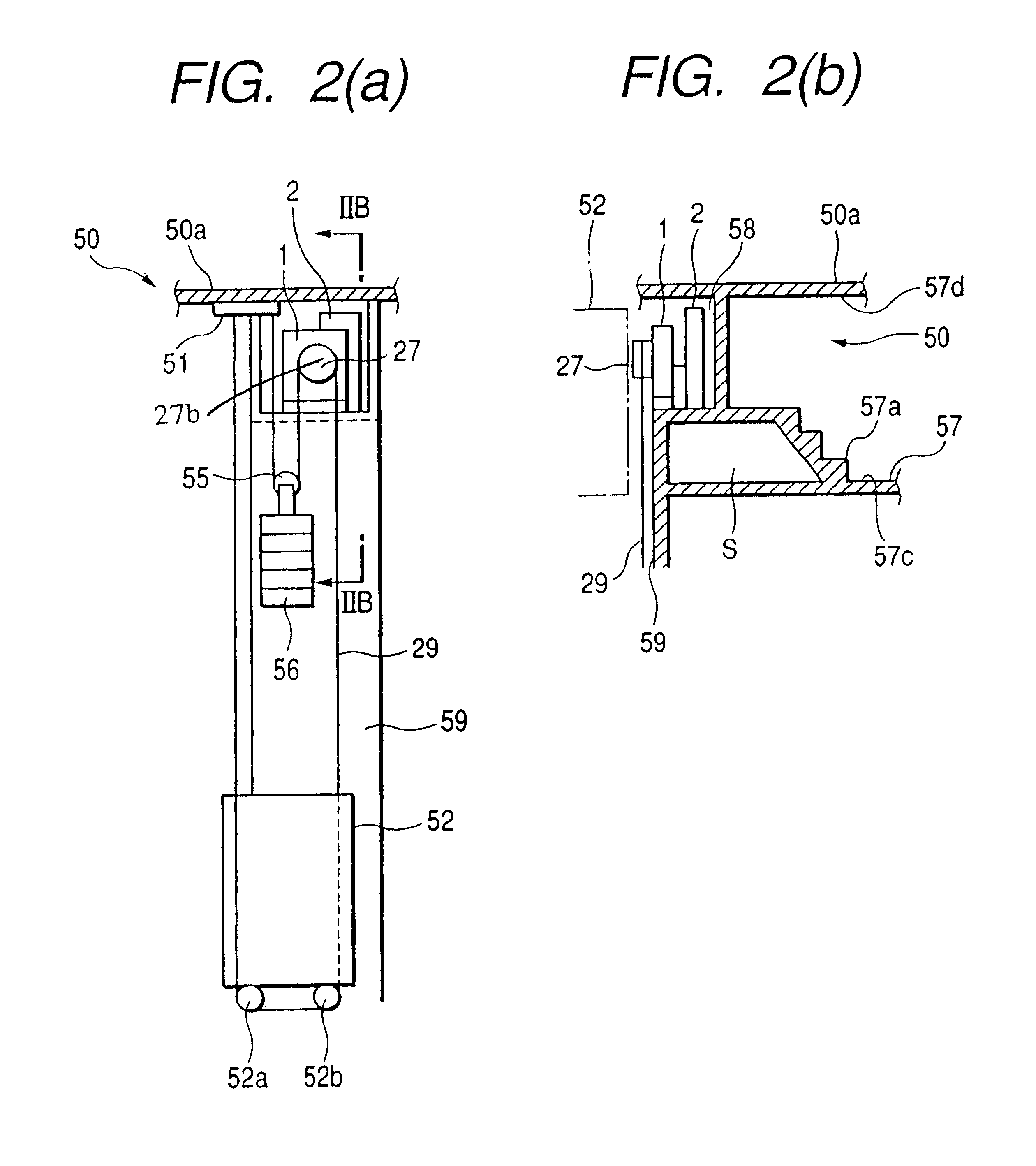
[0008]According to the elevator apparatus of the invention, because the actuating device is installed in the machine room provided on the top floor of the building in which the ascending and descending cage is disposed, and the machine room faces with the elevator passage for the ascending and descending cage, the elevator apparatus can be constructed in a smaller space and composed of less components, without employing the rope pulleys or the deflecting sheaves as in the prior art. Accordingly, the cost can be lowered. It is no more necessary that the ceiling of the top floor is set high unnecessarily. Further, because a height of the machine room is low, an effective space on the top floor of the building can be secured.

Problems solved by technology

Recently, comparatively tall buildings relative to areas of grounds have been often built, because there are many cases where the grounds are limited in a city and the like.
In such a tall building, an elevator is particularly required to ascend to high floors, and it is a problem how this elevator should be installed.
However, in such a structure, there has been a problem that a first and a second rope pulleys are required to be provided in an upper part of the elevator passage in order to transmit a power from the actuating device to the ascending and descending cage by way of the rope, which incurs a complexity of the structure and an increase of the cost.
In such a prior art, there has been another problem that in the structure in which the actuating device is provided below the elevator passage, an underground room having a size for accommodating the actuating device must be provided underground, and the cost will be further increased.
Moreover, there has been a further problem that in case a determined amount of space is provided above the elevator passage for a fear of an overrun of the ascending and descending cage, and rope pulleys are mounted in the upper part of the elevator passage, a ceiling of the top floor of the building will be higher.
However, such a structure has also a problem that four deflecting sheaves are required above the ascending and descending cage, which incurs a complexity of the structure and an increase of the cost, similarly to the above described prior art.

Method used


Image

  • Elevator apparatus
  • Elevator apparatus
  • Elevator apparatus

Examples


Embodiment Construction

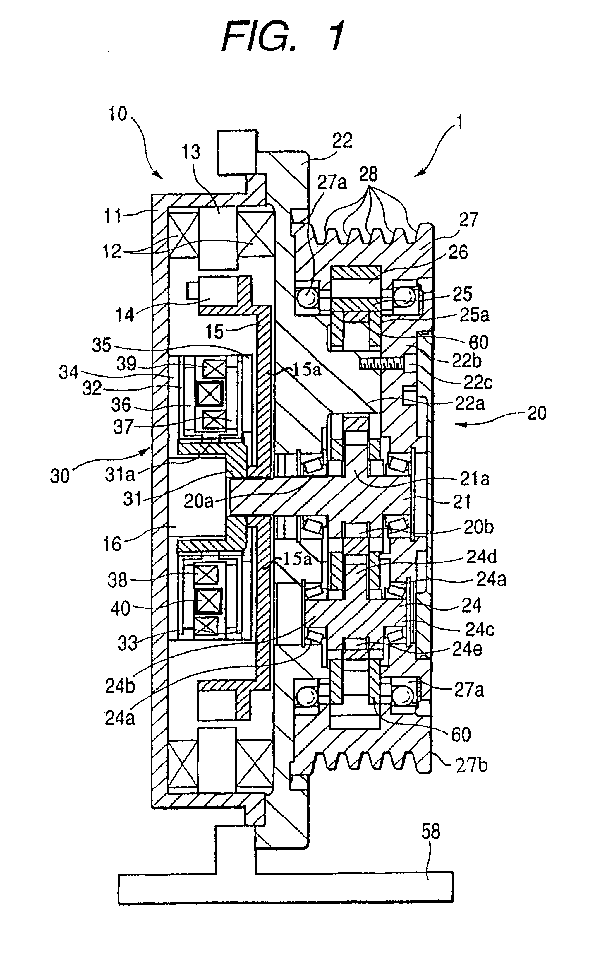
[0012]Hereunder, a mode for carrying out the invention will be described referring to the drawings. FIG. 1 is a sectional side view of an actuating device 1 for an elevator illustrating an embodiment according to the invention.

[0013]As shown in FIG. 1, the actuating device 1 for the elevator includes a motor assembly 10, a speed-reducer 20 adapted to reduce rotation speed of an input shaft 21 which is driven to rotate by means of the motor assembly 10 to transmit the rotation, and a brake assembly 30.

[0014]The motor assembly 10 has, in a housing 11 of the motor assembly 10, a coil 12, a stator 13 disposed adjacent to the coil 12, a rotor 14, a rotary disc 15 fixed to the rotor 14 and having its center part splinedly connected to the input shaft 21 to rotate therewith. An encoder 16 detects a number of rotations of the input shaft 21. The housing 11 is fixed to a support member 22 of the speed-reducer 20. The rotary disc 15 includes a support web 15a that extends radially from the in...


PUM


Abstract

An elevator apparatus has an actuating device including a sheave around which a rope engaged with an ascending and descending cage is wound and a driving section for rotating the sheave. The sheave is adapted to rotate to move the rope with its rotation. The actuating device is installed in a machine room provided on a top floor of a building in which the ascending and descending cage is disposed. The machine room faces with an elevator passage for the cage.

Description

BACKGROUND OF THE INVENTION[0001]The present invention relates to an elevator apparatus for moving an ascending and descending cage of an elevator upward and downward.[0002]Recently, comparatively tall buildings relative to areas of grounds have been often built, because there are many cases where the grounds are limited in a city and the like. In such a tall building, an elevator is particularly required to ascend to high floors, and it is a problem how this elevator should be installed. Although an elevator passage through which the ascending and descending cage of the elevator passes must be provided in a manner a passing through respective floors, an actuating device for moving the elevator upward and downward can be installed at an optional position to some degree.[0003]By the way, it is disclosed in Japanese Publication of unexamined Utility Model Application No. JP-A-59-40276U, for example, that the actuating device is provided below the elevator passage or at a side of the e...

Claims


Application Information

Patent Timeline
IPC IPC(8): B66B7/00B66B11/00
CPCB66B11/0015B66B5/18B66B11/004B66B11/0075B66B11/04
Inventor MIYOSHI, HIROYUKIKUGA, TAKASHI
Owner TEIJIN SEIKI CO LTD
Learn More