Vertical takeoff and landing apparatus

a vertical takeoff and landing apparatus technology, applied in vertical landing/take-off aircraft, aircraft navigation control, transportation and packaging, etc., can solve the problems of inability to take effective countermeasures or minute counteractive actions, the flight posture or attitude of the pilot collapses or changes, and the pilot's body or weight is extremely low in response, so as to eliminate any fear of defective or poor fuel supply, excellent maneuverability and postural stability of the airfram

Active Publication Date: 2005-11-29
TOYOTA JIDOSHA KK
View PDF40 Cites 32 Cited by
  • Summary
  • Abstract
  • Description
  • Claims
  • Application Information

AI Technical Summary

Benefits of technology

[0018]Accordingly, the present invention is intended to solve the problems as referred to above, and has for its object to provide a vertical takeoff and landing apparatus which is excellent in the maneuverability and the postural stability of an airframe, and has the function of protecting a pilot from the impact of an accident, and is capable of stable flight when hovering near a building, while eliminating any fear of defective or poor fuel supply or fuel remaining unused.
[0028]According to this arrangement, the fuel in the fuel tank can be fully used up, and the pilot can exactly know the amount of fuel remaining in the fuel tank, thus making it easy to perform flight control.
[0030]With this arrangement, the apparatus can travel on the ground, so the range of movement thereof can be expanded or increased, thus making the apparatus particularly suitable for disaster relief, etc.
[0036]Preferably in the vertical takeoff and landing apparatus according to the first or second aspect of the present invention, each of the air intake port sections may be covered with a net member. According to such an arrangement, accidents such as a defective operation due to the suction or inhalation of foreign matters can be prevented in advance.
[0037]A flying machine having a person transportation function according to the present invention is excellent in maneuverability and postural stability, has the function of protecting the pilot, and is able to make extremely stable flight even in case of hovering near a building.

Problems solved by technology

Even in this case, however, minute counteractive actions or effective countermeasures might not sometimes be able to be taken unless someone actually visits the site to be surveyed.
The one-person vertical takeoff and landing apparatuses as described above do not have selfstability or autostability such as that of airplanes or helicopters, so the flight posture or attitude thereof collapses or changes greatly if posture or attitude control is not carried out.
However, the method of shifting the body or weight of the pilot is extremely low in response, so it is impossible to perform detailed or minute attitude control.
In addition, there arises a characteristic that the airframe is caused to momentarily move, due to a reaction generated in the course of the movement of the body or weight, in a direction opposite to the direction in which it should be originally controlled to be moved.
Thus, the control due to the body or weight shift lacks practical use, and its improvement is desired.
Firstly, since there is provided no means for protecting passengers at the time of emergency landing or the like, it is necessary to obviate the fear of passenger injuries even in a small accident.
Secondly, since they are constructed such that a propeller slipstream and an air intake port are oriented directly toward the pilot, an extremely strong wind will blows against the pilot while flying. Therefore, in case of low temperatures or the like, the temperature of the pilot will be rapidly deprived so that the pilot might sometimes be subjet to frostbite, etc. Accordingly, it is required to improve such a situation.
Thirdly, since a fuel tank is fixedly attached to the airframe, the fuel in the fuel tank is caused to move due to the tilting of the airframe, so that a defective or poor fuel supply might be caused or the fuel might be left in the fuel tank without being fully used up. Thus, fuel control is important in view of the limited flight time of small flying crafts.
Fourthly, in cases where a flying craft is hovering near a building, it is likely to make contact with or too far away from the building because of the influences of the instability factor of the airframe itself, crosswinds and the like. This is a serious problem in fire rescue operations in high-rise buildings, etc., and improvements thereof are strongly required.

Method used


Image

  • Vertical takeoff and landing apparatus
  • Vertical takeoff and landing apparatus
  • Vertical takeoff and landing apparatus

Examples


embodiment 1

[0087]First, a vertical takeoff and landing apparatus according to a first embodiment of the present invention will be described while referring to FIG. 1 through FIG. 15.

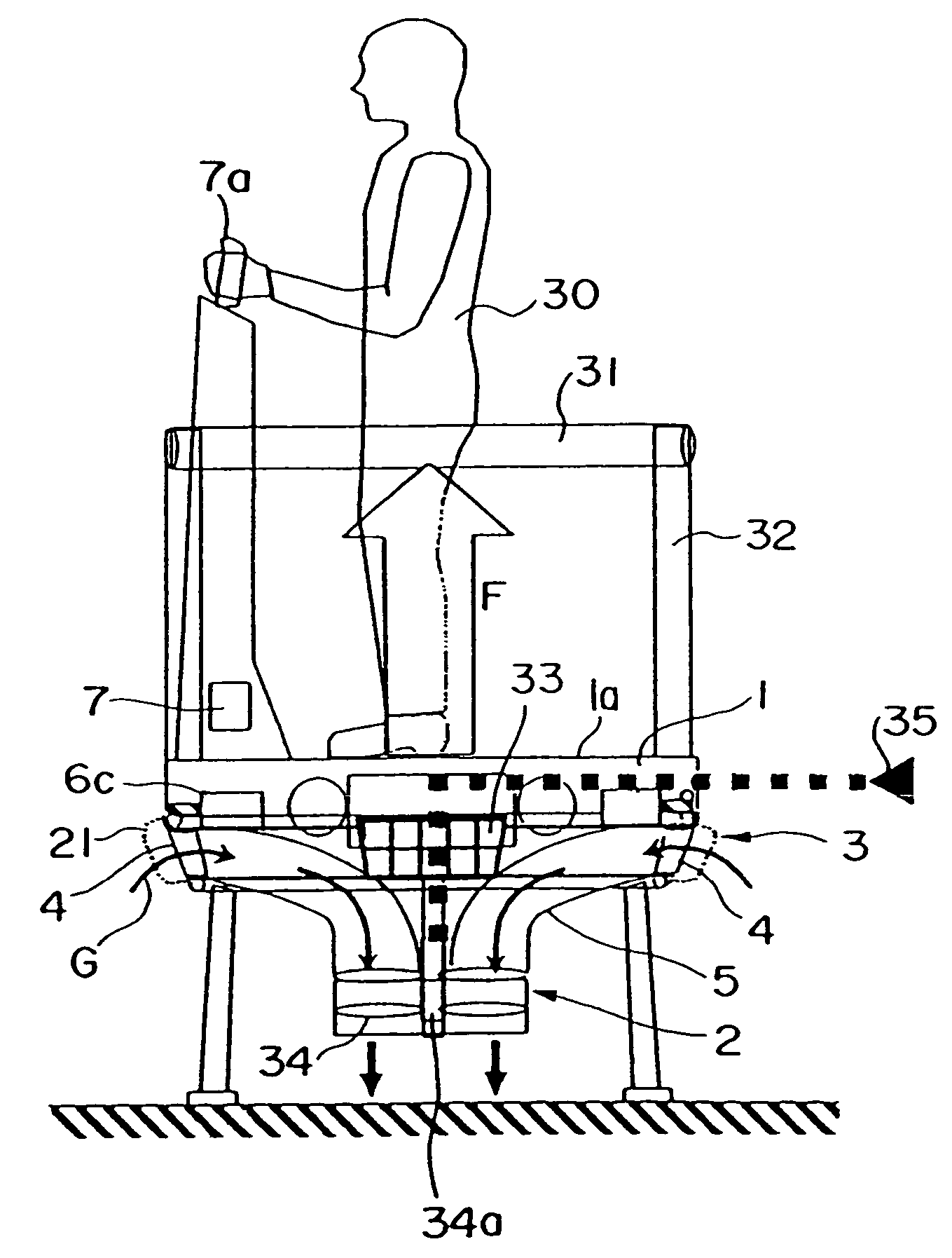
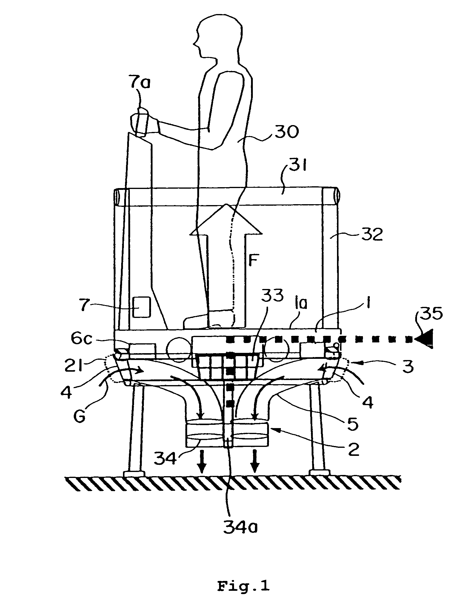
[0088]This vertical takeoff and landing apparatus is suitable for use with one person, and has its body or airframe 1 formed into substantially a disk-shaped configuration. The airframe 1 has an upper surface 1a in the form of a flat surface, on which an operator or pilot 30 can stand for controlling the apparatus. A plurality of poles 32 are arranged upright on the upper surface 1a of the airframe 1, with a guard ring 31 of an annular shape being mounted on a tip end of each pole 32. This guard ring 31 is provided for protecting the pilot 30 and preventing him from falling off from the airframe 1.

[0089]A propulsion device 2 for generating propulsive force F in a vertically upward direction is arranged in the center of and the inside of the airframe 1. This propulsion device 2 can be adopted either of an externally...

embodiment 2

[0104]A second embodiment of the present invention will be described while referring to FIG. 16 through FIG. 28. In these figures, the same or corresponding parts of this embodiment as those of the first embodiment are identified by the same symbols while omitting an explanation thereof.

[0105]In this embodiment, a plate 8 of a wing or airfoil cross section is provided at each section of the air intake port 4 instead of each shutter part 6. An asymmetrical wing or airfoil of the Clark Y type or the like is suitable for each plate 8, which is provided at its both ends with a pair of support members 9 which are pivotally or rotatably supported on the both side walls of a corresponding section of the air intake port 4 so as to support this plate 8 at an arbitrary angle of attack. That is, each support member 9 is a universal pivot, and the plates 8 are arranged in such a manner that the angle of attack and the angle of tilt or inclination of each plate 8 can be individually changed by t...

embodiment 3

[0111]A third embodiment of the present invention will be described while referring to FIG. 29 through FIG. 33. In these figures, the same or corresponding parts of this embodiment as those of the above-mentioned first and second embodiments are identified by the same symbols while omitting an explanation thereof.

[0112]This embodiment relates to a structure to protect the pilot 30, and includes airbags 12, 12a, 15 attached to an outer side of the guard ring 31, the outside surface of the airframe 1, and tip ends of a plurality of legs 40 mounted on a lower surface of the airframe 1, respectively.

[0113]An annular storage member 11 arranged to surround the pilot 30 is mounted to the outer side of the guard ring 31. This storage member 11 comprises a cover of a semi-circular cross section for receiving therein the airbag 12, as shown in FIG. 31 and FIG. 33. FIG. 30 and FIG. 31 illustrate the state of the airbag 12 being received therein, i.e., being not expanded, whereas FIG. 32 and FI...


PUM


Abstract

A vertical takeoff and landing apparatus is excellent in the maneuverability and postural stability of its airframe, serves to protect a pilot from an impact when landing, and can make extremely stable flight when hovering near a building. An airframe has a propulsion device for generating propulsive force in a vertically upward direction, and a side wall surface surrounding the propulsion device. An air intake port has a plurality of divided air intake port sections formed on the side wall surface of the airframe. A duct part connects the air intake port sections and the propulsion device with one another. A shutter part is provided at each air intake port section for adjusting an amount of air flowing therein. A control unit adjusts the degree of opening of each shutter part in accordance with an operation of a control stick, so that the airframe can be moved in an arbitrary direction.

Description

BACKGROUND OF THE INVENTION[0001]1. Field of the Invention[0002]The present invention relates to a vertical takeoff and landing apparatus, and more particularly, to a small one capable of carrying a few persons thereon.[0003]2. Description of the Related Art[0004]Dangerous places such as disaster sites or the like for people to access can be explored or surveyed by using an unmanned flying craft or vehicle as described in a first patent document (Japanese Patent Application Laid-Open No 11-115896) for example. Such a flying craft has a rotary blade or blades, and is able to perform motions such as horizontal movements, vertical movements, rotation in the yaw direction, etc. Accordingly, it is considered that a variety of kinds of information can be gathered by using such a flying craft as required.[0005]Even in this case, however, minute counteractive actions or effective countermeasures might not sometimes be able to be taken unless someone actually visits the site to be surveyed. ...

Claims


Application Information

Patent Timeline
Patent Type & Authority Patents(United States)
IPC IPC(8): B64C25/58B64C29/00B64C27/20B64C39/02B64D25/02
CPCB64C27/20B64C39/026
Inventor ISHIBA, MASATSUGU
Owner TOYOTA JIDOSHA KK
Why Eureka
Try Eureka