Method and apparatus for treating presbyopia

Inactive Publication Date: 2005-11-29
HIGH POWER PERIPHERAL CORNEA CORP
View PDF4 Cites 16 Cited by
  • Summary
  • Abstract
  • Description
  • Claims
  • Application Information

AI Technical Summary

Benefits of technology

[0015]A further objective is to provide an improved method which does not require expensive or difficult modifications to the existing eye treatment apparatus.
[0016]Yet a furth

Problems solved by technology

As a person gets older, the lens in his eye and its supporting structure, such as the ligaments or zonules lose elasticity and he slowly loses his ability to accommodate.
As a result he can no longer see close objects clearly, i.e., he suffers near vision deficiency.
One disadvantage is that some persons can get dizzy fro

Method used


Image

  • Method and apparatus for treating presbyopia
  • Method and apparatus for treating presbyopia
  • Method and apparatus for treating presbyopia

Examples


Example

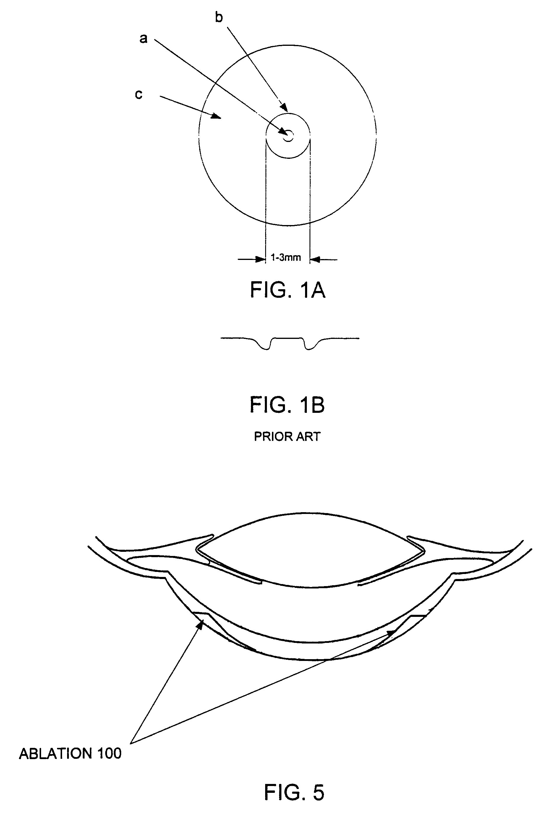
[0029]Referring first to FIG. 1A, as mentioned above, prior to the present invention it was believed that for near vision the eye makes use of light entering the cornea through a central zone b having a diameter of about 3 mm. Accordingly, most prior art techniques consist of ablating tissue at various depths in the cornea in a central zone b extending between 1 mm and about 3 mm. A small spot of about 1 mm is not ablated. More importantly, the annular zone c extending from about 5 mm to 10+mm is not substantially ablated during this treatment. FIG. 1B shows a typical prior art profile resulting from central ablation. As can be seen in this profile, the central ablation is concentrated in the vicinity of the outer edge of zone b, i.e., at about 3 mm.

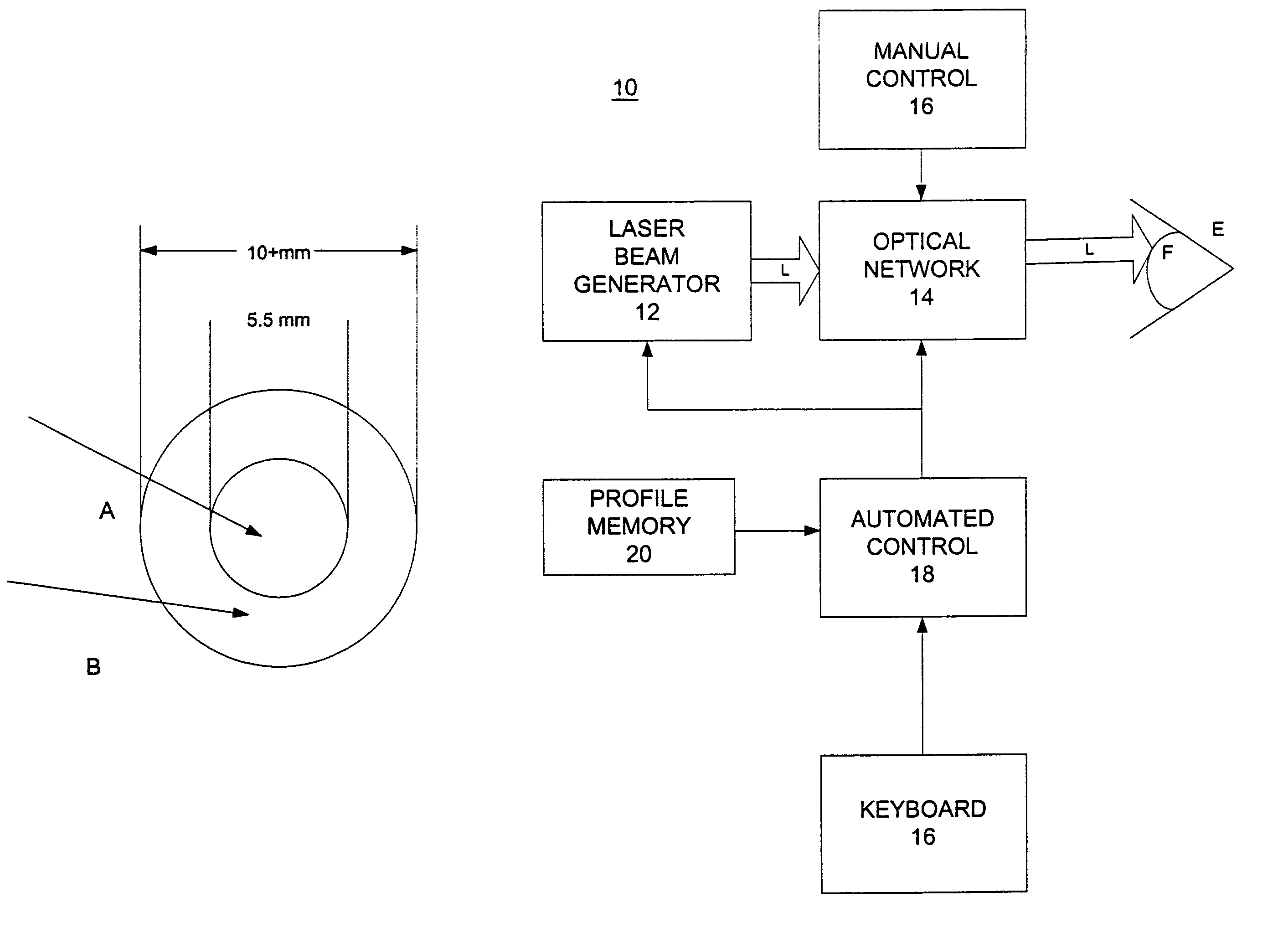
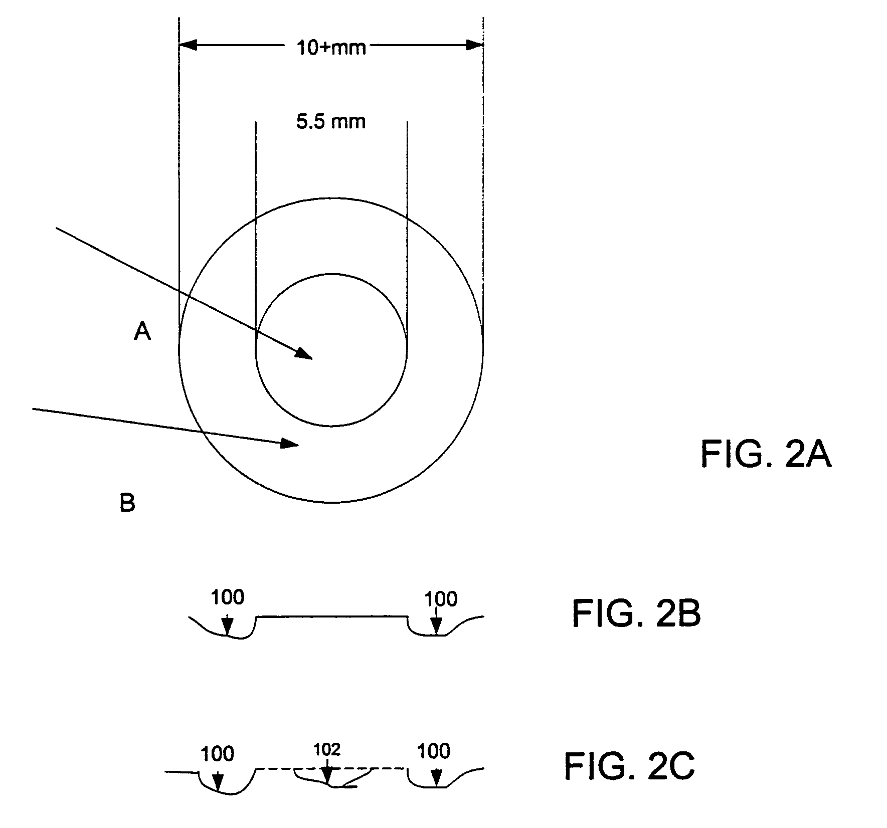
[0030]According to the present invention, the treatment should not be applied to the central zone of the cornea but to its outer peripheral zone. FIG. 2A shows a schematic view of the cornea with a central zone A of about 5.5 mm and an a...


PUM


Abstract

An apparatus and method are disclosed for treating near vision loss or deficiency, such as presbyopia. In contrast to conventional techniques, a peripheral ablation is provided in an annular zone of the cornea ranging from 5.5 to about 10+mm to increase the dioptic power of this peripheral zone. The central zone disposed within the peripheral zone of the cornea is left untreated, is corrected for other vision deficiencies or is corrected so that it reverts to its characteristics prior to the peripheral ablation.

Description

RELATED APPLICATIONS[0001]This application is a continuation of application Ser. No. 09 / 841,674 filed Apr. 24, 2001, now U.S. Pat. No. 6,740,078, the content of which is incorporated herein by reference.BACKGROUND OF THE INVENTION[0002]A. Field of Invention[0003]This invention pertains to a method and apparatus for treating eye disorders associated with imperfections of a patient's eye and its disability to accommodate for near vision. More particularly, the present invention pertains to a method and apparatus for treatment of presbyopia by shaping an annular or extreme peripheral portion of the patient's cornea to increase its refractive power, preferably using automated laser equipment.[0004]B. Description of the Prior Art[0005]Normally, a sharp image of an object is produced by a person's eye when the image is correctly projected on the retina. The process of focusing the image on the retina is referred to as accommodation, and it describes varying the curvature of the lens to ch...

Claims


Application Information

Patent Timeline
IPC IPC(8): A61B18/20A61F9/007A61F9/01A61N5/06
CPCA61F9/008A61F9/00808A61F2009/00872
Inventor TAMAYO, GUSTAVO E.SERRANO, MARIO G.
Owner HIGH POWER PERIPHERAL CORNEA CORP
Why Eureka
Try Eureka