
Image processing apparatus and method for correcting print data so as to reduce density unevenness, and image forming system

a technology of image processing and print data, applied in the field of image processing apparatus and method, can solve the problems of reducing the number of tone levels of the input image, affecting the output time, and avoiding band-like density unevenness, and achieve the effect of suppressing density unevenness in the output in a simple manner

Inactive Publication Date: 2005-11-29
CANON KK
View PDF5 Cites 4 Cited by
  • Summary
  • Abstract
  • Description
  • Claims
  • Application Information

AI Technical Summary

Benefits of technology

[0006]Accordingly, an object of the present invention is to provide an image processing apparatus and method in which it is possible to suppress density unevenness in the output of an image forming apparatus in a simple manner.

Problems solved by technology

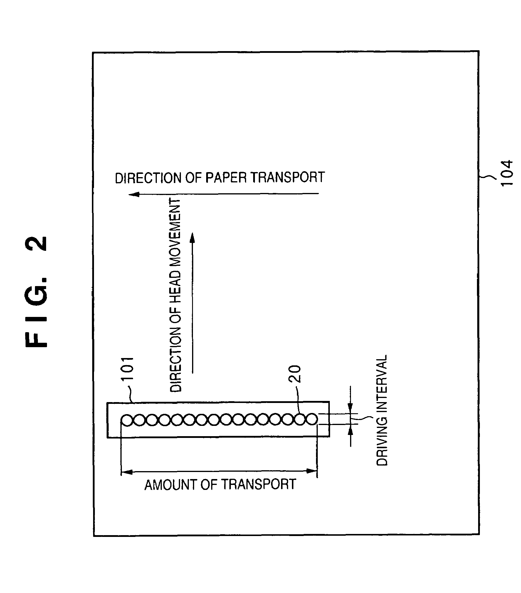
In an arrangement of this type, it is difficult to avoid band-like density unevenness caused by variations in the spacing between the print elements and by the mechanical precision with which the printhead and print medium are moved.
However, when use is made of a method of correcting density unevenness using the head shading correction, the number of tone levels of the input image is reduced by the correction and output time is prolonged.

Method used


Image

  • Image processing apparatus and method for correcting print data so as to reduce density unevenness, and image forming system
  • Image processing apparatus and method for correcting print data so as to reduce density unevenness, and image forming system
  • Image processing apparatus and method for correcting print data so as to reduce density unevenness, and image forming system

Examples


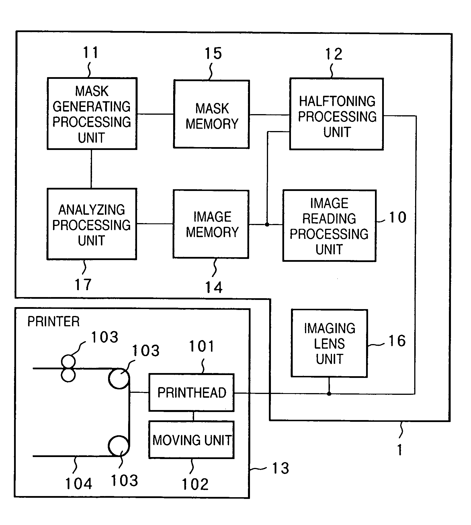
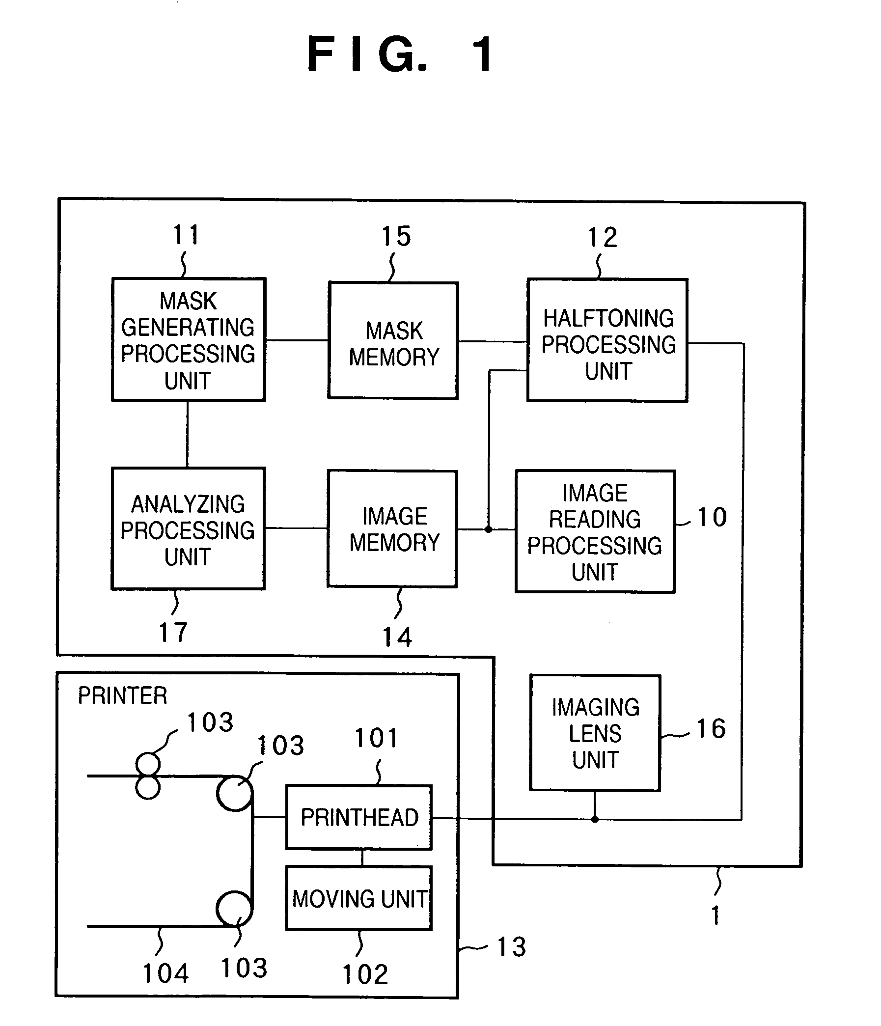
first embodiment

[0028](Overall Construction)

[0029]FIG. 1 is a block diagram illustrating an example of the configuration of an image forming system obtained by connecting an image processing apparatus 1 according to this embodiment of the invention and a printer 13 serving as an image forming apparatus.

[0030]The image processing apparatus 1 and printer 13 are connected by a printer interface or network interface, neither of which are shown.

[0031]As shown in FIG. 1, the image processing apparatus 1 includes an image reading processing unit 10 for reading output image; a mask generating processing unit 11 for generating a threshold-value mask; a halftoning processing unit 12 for halftoning an input image; an image memory 14 for storing as input image and a read image; a mask memory 15 for storing the threshold-value mask; a test image memory 16 for storing a test image that is for measuring the characteristic of the output device; and an analyzing processing unit 17 for analyzing the characteristic o...

second embodiment

[0056]The first embodiment corrects for a variation in density for each print element. In a second embodiment, it is possible to correct for printing position deviation for each print element.

[0057]The procedure for correcting and outputting an image using the image processing apparatus shown in FIG. 1 will be described again.

[0058]First, a test image is output in order to measure the characteristics of the output device. FIG. 10 illustrates the details of the test image. As in FIG. 3, a white square 30 indicates that the pixel is not printed and a black square 31 indicates that the pixel is printed. As will be apparent from FIG. 10, the test image in this embodiment is composed of blocks a to d having patterns that differ from one another. Further, the size of the test image is 48 pixels horizontally and 32 pixels vertically, and the test image is printed on the print medium by scanning the printhead of FIG. 2 two times.

[0059]Next, the result of outputting the test image is read by...


PUM


Abstract

Disclosed are an image processing apparatus and method in which it is possible to suppress density unevenness in the output of an image forming apparatus in a simple manner. A test image is printed out by a printer (13), the printout is read by an image reading processing unit (10), and an analyzing processing unit (17) detects the output characteristic (density unevenness, printing position deviation, etc.) of each of a plurality of print elements possessed by the printhead of the printer. A mask generating processing unit (11) generates a threshold-value mask which reflects the output characteristics detected by the analyzing processing unit and stores the mask in a mask memory (15). A halftoning processing unit (12) outputs image data to the printer after the image data is subjected to halftoning utilizing the threshold-value map that has been stored in the mask memory.

Description

FIELD OF THE INVENTION[0001]This invention relates to an image processing apparatus and method. More particularly, the invention relates to an image processing apparatus and method having a mechanism for correcting output data so as to reduce density unevenness in an output generated by an image forming apparatus such as a printer.BACKGROUND OF THE INVENTION[0002]Conventional devices for forming an image on a recording medium such as paper or an OHP sheet have been proposed in a form having a mounted printhead that operates based on various printing techniques. Examples of these printing techniques are the wire dot, thermosensitive, thermal transfer and ink-jet techniques. All of these techniques generally employ a printhead in which a plurality of print elements are integrated in order to raise printing efficiency.[0003]In an arrangement of this type, it is difficult to avoid band-like density unevenness caused by variations in the spacing between the print elements and by the mech...

Claims


Application Information

Patent Timeline
Patent Type & Authority Patents(United States)
IPC IPC(8): B41J29/46B41J2/52G06K15/00H04N1/401H04N1/405
CPCH04N1/4015H04N1/405
Inventor USHIRODA, ATSUSHI
Owner CANON KK
Learn More