Phase-shifted resonant converter having reduced output ripple

Active Publication Date: 2005-11-29
BEL POWER SOLUTIONS INC
View PDF10 Cites 57 Cited by
  • Summary
  • Abstract
  • Description
  • Claims
  • Application Information

AI Technical Summary

Benefits of technology

[0011]The first and second resonant circuits each further comprises an inductor, a transformer having a primary winding in series with the inductor, and first and second capacitors in series with the primary winding and connected across an input voltage source. In an alternative embodiment of the invention, an overvoltage condition of at least one of the first and second resonant converter circuits is prevented by including first and second diodes coupled in parallel respectively with the first and second capacitors. The diodes serves to couple to ground e

Problems solved by technology

A drawback of resonant converter circuits is that the output current generally has ripple that is unacceptable for certain applications.
The filter capacitor must remove a relatively large portion of the current delivered from the resonant circuit, resulting in inefficiency of the resonant converter circuit and increasing the size and capacity of the filter capacitor.
These drawbacks are further exacerbated when the output power or output current of the resonant converter circuit is very high.
Another drawback of resonant converter circuits is that they have limited output voltage regulation window.
If the resonant circuit has

Method used


Image

  • Phase-shifted resonant converter having reduced output ripple
  • Phase-shifted resonant converter having reduced output ripple
  • Phase-shifted resonant converter having reduced output ripple

Examples


Embodiment Construction

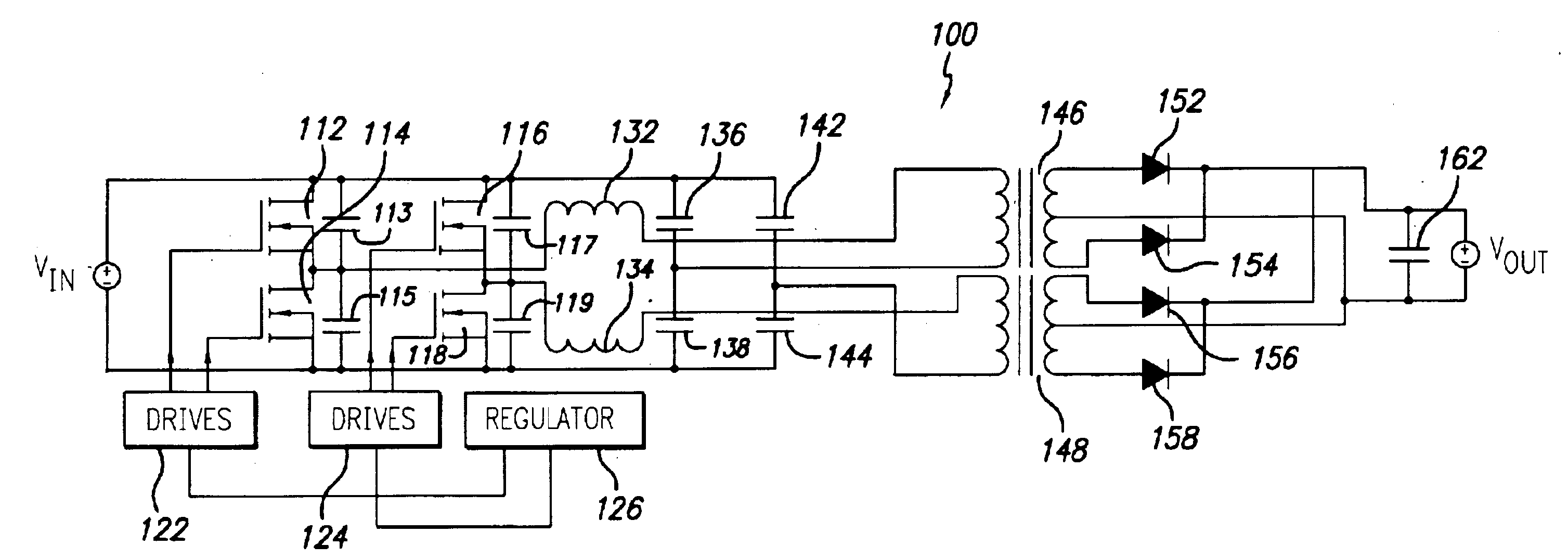
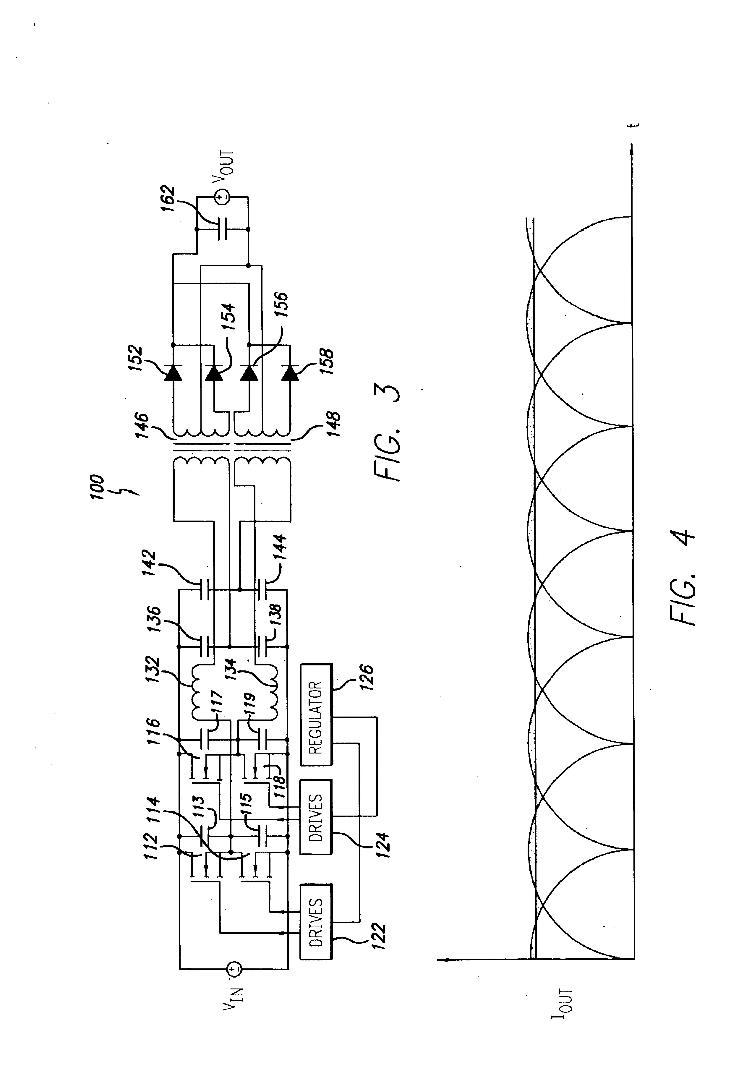
[0020]The present invention provides a resonant converter circuit having reduced ripple current for use in high output power applications and that has improved voltage regulation. In the detailed description that follows, like element numerals are used to describe like elements illustrated in one or more of the figures.

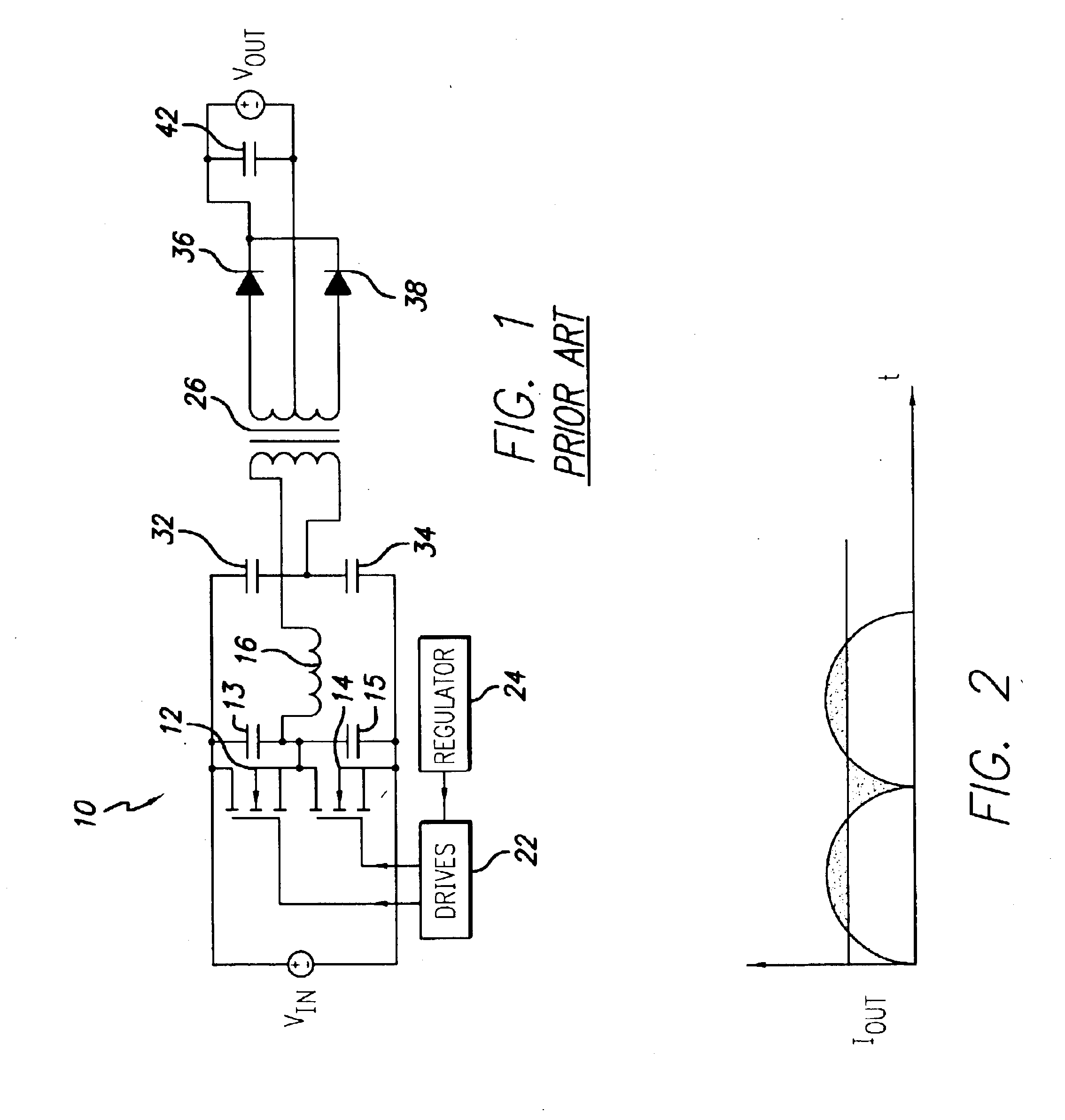
[0021]FIG. 1 depicts a resonant converter circuit 10 in accordance with the prior art. The resonant converter 10 converts an input DC voltage Vin to an output DC voltage Vout applied to a load (not shown). The resonant converter 10 includes a pair of power switches 12, 14, typically provided by MOSFET devices. The drain terminal of the high side power switch 12 is coupled to the input voltage Vin, the source terminal of the low side power switch 14 is connected to ground, and the respective source and drain terminals of the power switches 12, 14 are coupled together to define a phase node. The phase node is coupled to a resonant circuit that includes inductor 16, the ...


PUM


Abstract

A power converter comprises a pair of resonant converter circuits coupled together in parallel and operated at respective switching frequencies that are out of phase. The power converter includes a first resonant converter circuit and a second resonant converter circuit operatively coupled together. The first resonant converter circuit includes at least one power switch adapted to convey power to a first resonant circuit and a first rectification stage adapted to rectify the conveyed power from the first resonant circuit. The second resonant converter circuit includes at least one power switch adapted to convey power to a second resonant circuit and a second rectification stage adapted to rectify the conveyed power from the second resonant circuit. A filter capacitor is coupled to the first and second rectification stages to provide DC output power therefrom. A regulator is operatively coupled to the first and second resonant converters to control switching frequency of the power switches, such that the switching frequency of the at least one power switch of the second resonant converter is shifted in phase with respect to the switching frequency of the at least one power switch of the second resonant converter. In a preferred embodiment, the switching frequency of the at least one power switch of the second resonant converter is shifted in phase by approximately 90° with respect to the switching frequency of the at least one power switch of the second resonant converter.

Description

BACKGROUND OF THE INVENTION[0001]1. Field of the Invention[0002]The present invention relates to switched mode power converter circuits, and more particularly, to a phase-shifted half bridge resonant converter that provides a DC output voltage having minimal ripple.[0003]2. Description of Related Art[0004]Switched mode power converters are known in the art to convert an available direct current (DC) level voltage to another DC level voltage. A switched mode power converter provides a regulated DC output voltage to a load by selectively storing energy in an inductor coupled to the load by switching the flow of current into the inductor. A resonant converter is one particular type of switched mode power converter that includes a resonant circuit including a capacitor and an inductor. Current is periodically delivered to the resonant circuit by operation of one or more power switches typically provided by MOSFET transistors. The load may be isolated from the resonant circuit using a tr...

Claims


Application Information

Patent Timeline
IPC IPC(8): H02M3/28
CPCH02M3/285Y02P80/10
Inventor APELAND, INGVARMYHRE, ROAR
Owner BEL POWER SOLUTIONS INC
Why Eureka
Try Eureka