Electric braking of machinery with a plurality of inverter-fed motors

a technology of inverter-fed motors and electric braking, which is applied in the direction of motor/generator/converter stoppers, multiple dynamo-motor starters, dynamo-electric converter control, etc., can solve the problem of fast stoppage of load inertia, and achieve the effect of large current, fast stoppage of load inertia, and dissipation of the greatest amount of energy

Inactive Publication Date: 2009-03-31
BALDOR ELECTRIC COMPANY
View PDF7 Cites 12 Cited by
  • Summary
  • Abstract
  • Description
  • Claims
  • Application Information

AI Technical Summary

Benefits of technology

[0005]A system and method are provided whereby at least two motors driven by an inverter coupled to a DC bus are configured to alternate between regenerative and injection braking such that at least one motor is placed in regenerative braking mode and at least one motor is placed in motoring mode. In such a configuration, energy is simultaneously placed on and removed from the DC bus in a manner allowing a large current to flow in as many motors as possible. Consequently, this enables dissipating a greatest amount of energy in a shortest time period, resulting in fast stoppage of load inertia. Further, a system and method are provided for placing at least one motor in regenerative braking mode and at least one motor in DC injection mode, such that energy is simultaneously placed onto and removed from the DC bus, respectively. Further, a system and method are provided such that a single motor is alternated between regenerative braking and DC injection braking, such that energy is alternately placed onto and removed from the DC bus, respectively.
[0006]In all of these scenarios, a motor or motors may provide energy to and / or draw energy from a DC bus used to supply power to an inverter that drives the motor or motors. The regulation of the regenerative and injection braking regimes may permit effective braking of the inertial load, while avoiding overvoltage conditions on the DC bus.

Problems solved by technology

Consequently, this enables dissipating a greatest amount of energy in a shortest time period, resulting in fast stoppage of load inertia.

Method used


Image

  • Electric braking of machinery with a plurality of inverter-fed motors
  • Electric braking of machinery with a plurality of inverter-fed motors
  • Electric braking of machinery with a plurality of inverter-fed motors

Examples


Embodiment Construction

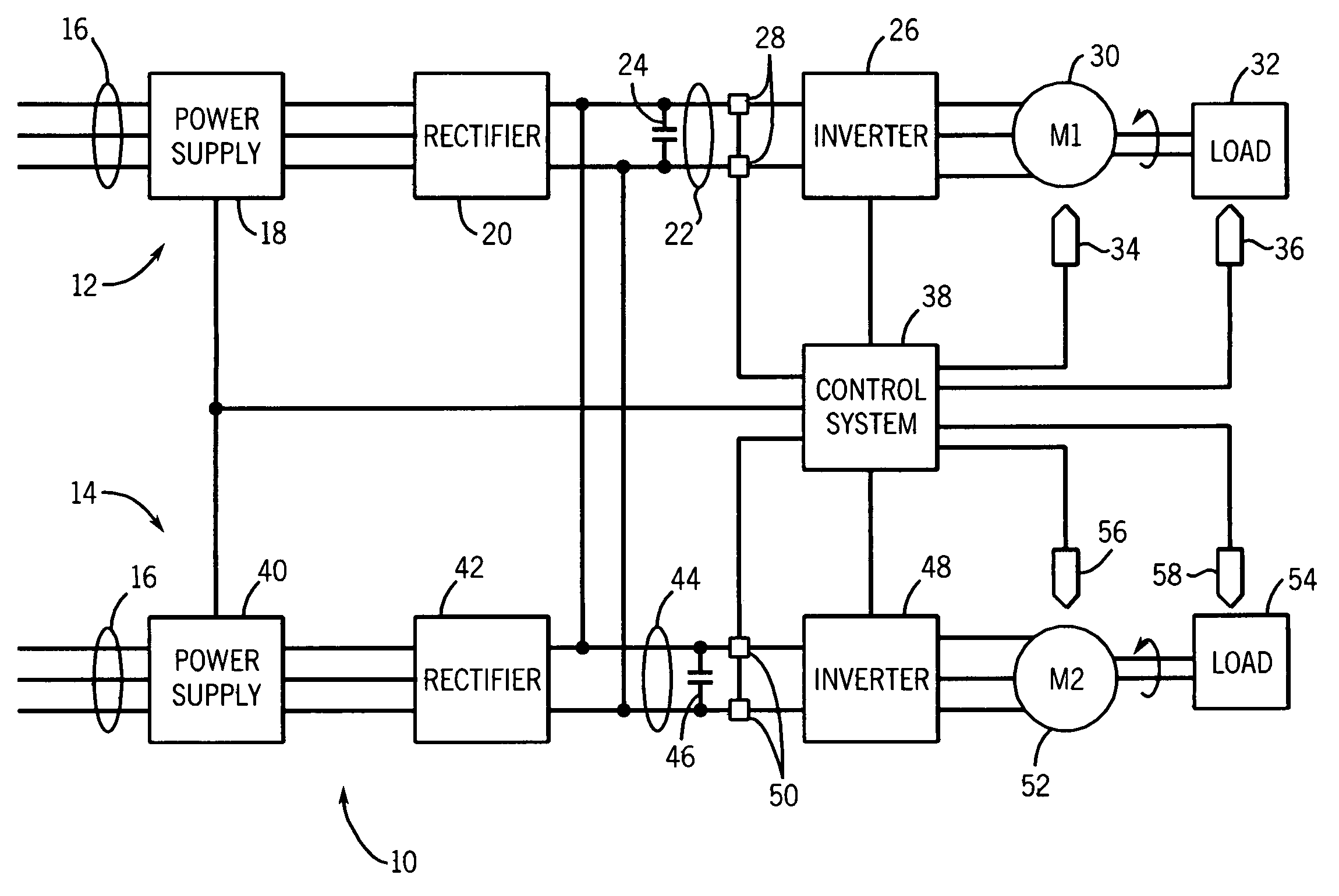
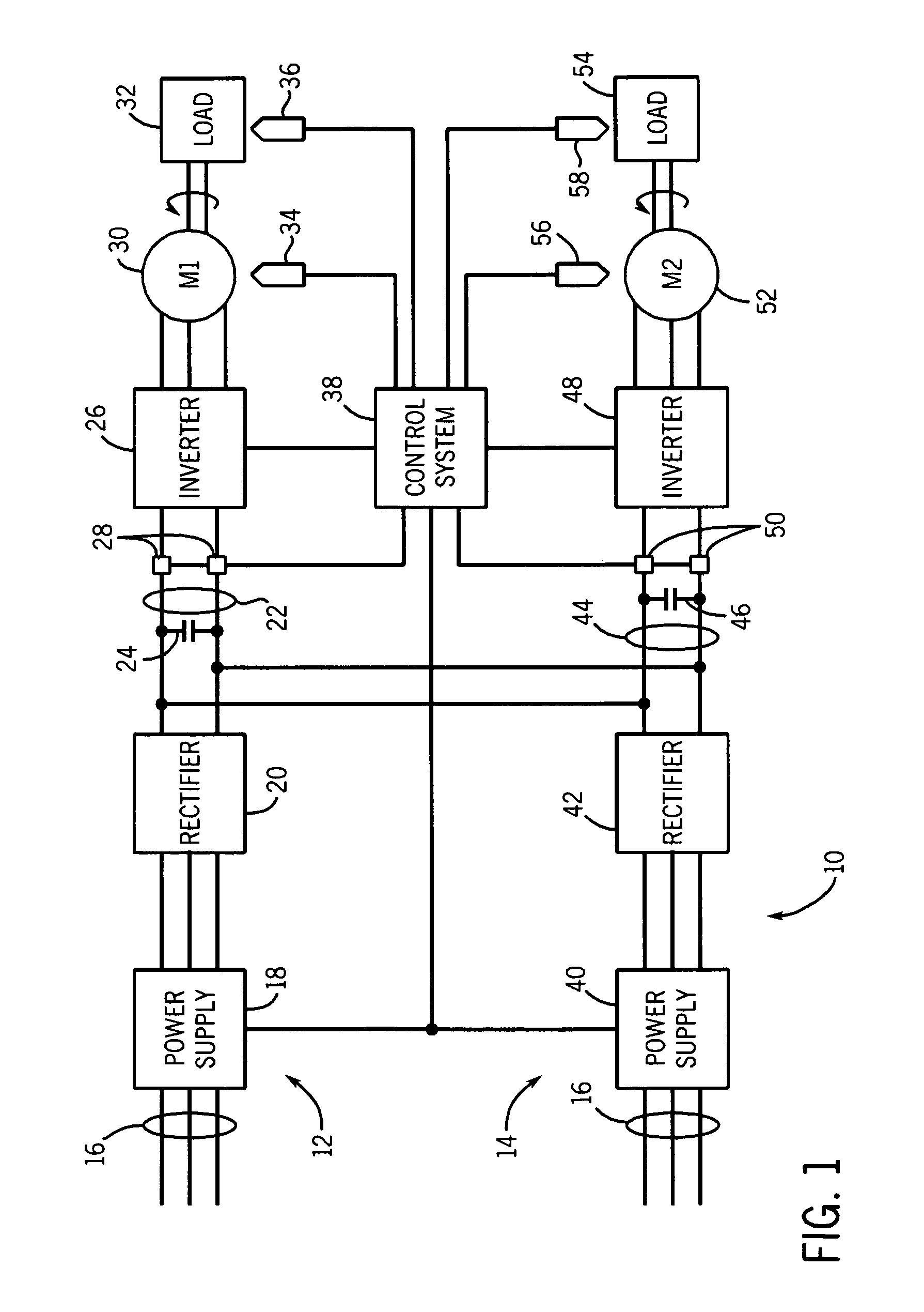
[0017]Referring now to the drawings, and particularly to FIG. 1, an inertial load drive system 10 is illustrated as including two motor drive systems 12 and 14 coupled via a common DC bus. The common DC bus connects motor system 12 and motor drive system 14 so as to facilitate DC power flow between systems 12 and 14. Motor drive systems 12 and 14 are coupled to inertial loads, such as vehicle tracks, wheels or axles, winches, cranes, manufacturing tools (e.g., pulleys or driven rolls) and so forth. Further, such systems may be driven by two motors or more such that each motor may drive a load disposed on a particular location (e.g., side) of the driven system. For example motors systems 12 and 14 may be used to motor a mining vehicle such that motor drive systems 12 may drive motor tracks disposed on one side of the vehicle, while motor drive system 14 drives tracks disposed on a second or opposite side of the vehicle. As further described below, during vehicle braking, energy trans...


PUM


Abstract

A system and method are provided whereby at least two motors driven by an inverter coupled to a DC bus are configured to alternate between regenerative and injection braking such that at least one motor is placed in regenerative braking mode and at least one motor is placed in motoring mode. Energy is simultaneously placed on and removed from the DC bus in a manner allowing a large current to flow in as many motors as possible, for fast stoppage of load inertia. At least one motor may be placed in regenerative braking mode and at least one motor in DC injection mode, such that energy is simultaneously placed onto and removed from the DC bus, respectively. Further, a single motor may be is alternated between regenerative braking and DC injection braking, such that energy is alternately placed onto and removed from the DC bus, respectively.

Description

BACKGROUND[0001]The invention relates generally to the control of electric motors. Particularly, this invention relates to electric motor braking using regenerative braking or direct current (DC) injection braking or a combination thereof.[0002]Electric motors, as used in many applications, typically require braking during their operation. For example, electric motors may be used in certain propulsion systems as prime movers, such as for vehicle drives. Further, during the course of motion of a vehicle or other inertial load it may be desirable to slow the load or bring it to a complete halt. More generally, braking systems and methods are an integral part of any system utilizing electric motors whose speeds may vary according to certain operational requirements. Many motors, particularly those driven at variable speeds, are driven by inverters, and braking may provide energy to a DC bus that provides power to the inverters.[0003]Methods of motor braking may utilize the motor itself...

Claims


Application Information

Patent Timeline
Patent Type & Authority Patents(United States)
IPC IPC(8): H02P5/00
CPCH02P3/18H02P3/24H02P5/74
Inventor MELFI, MICHAEL J.
Owner BALDOR ELECTRIC COMPANY
Why Eureka
Try Eureka