Device for and method of detecting interference waves

a technology of interference waves and devices, applied in the direction of transmission monitoring, network planning, electrical equipment, etc., can solve the problems of reducing line quality, improving the line quality of the upward line, and not being able to improve the line quality of the downward line from the base station to the mobile station, so as to improve the line quality of the downward line

Inactive Publication Date: 2005-11-29
MITSUBISHI ELECTRIC CORP
View PDF7 Cites 63 Cited by
  • Summary
  • Abstract
  • Description
  • Claims
  • Application Information

AI Technical Summary

Benefits of technology

[0017]The present invention is made to overcome the above problem. It is therefore an object of the present invention to provide an interference wave detecting device and an interference wave detecting method for use in a base station, capable of improving the line quality of the d...

Problems solved by technology

Interference waves having the same frequency as the received radio signal can reduce line quality.
While the prior art interference wave detecting device so constructed as mentioned above can tune from the current reception frequency adopted by either the first receiver 5 or the second receiver 9 to another reception frequency at which the level of interference waves is low, it suffers from a disadvantage that it can improve the line quality of the upward line from the mobile station to the base station, but cannot improve the line quality of the downward line from the base station to the mobile station, because it does not have a function of detecting the level of interference...

Method used


Image

  • Device for and method of detecting interference waves
  • Device for and method of detecting interference waves
  • Device for and method of detecting interference waves

Examples


first embodiment

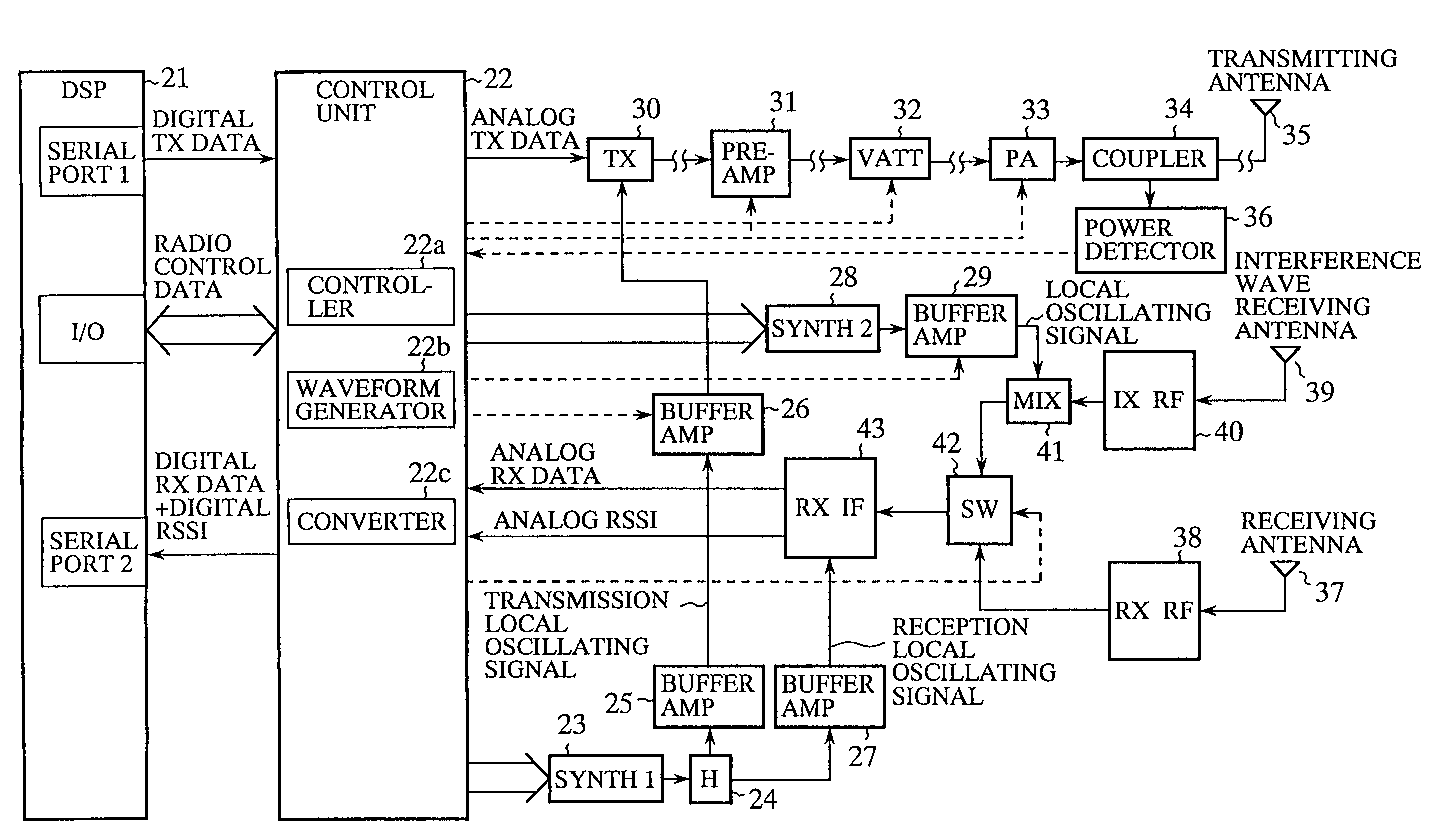
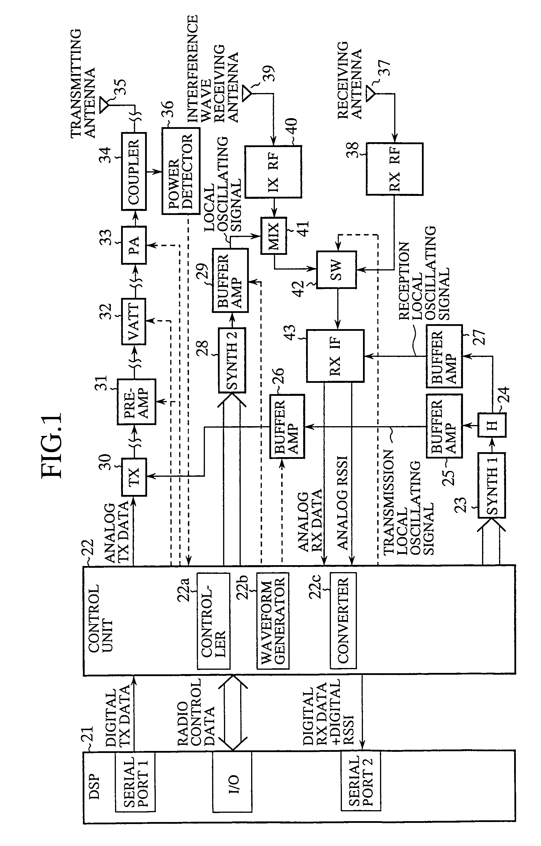
[0046]Referring next to FIG. 1, there is illustrated a block diagram showing the structure of an interference wave detecting device according to a first embodiment of the present invention, which can be disposed at a base station using TDMA. In the figure, reference numeral 21 denotes a digital signal processor or DSP disposed within the base station, and 22 denotes a control unit for converting digital data to be transmitted from the DSP 21 into an equivalent analog signal to be transmitted, for converting a received analog signal and a reception level analog signal, which have been furnished by a receiving IF unit 43, into equivalent received digital data and equivalent reception level digital data, respectively, and for controlling a preamplifier 31, a switch 42, and so on. The control unit 22 is provided with a controller 22a, a waveform generator 22b, and a converter 22c including both an A / D converter and a D / A converter.

[0047]Further, reference numeral 23 denotes a first synt...

second embodiment

[0117]Referring next to FIG. 7, there is illustrated a block diagram showing the structure of an interference wave detecting device according to a second embodiment of the present invention. In the figure, the same reference numerals as shown in FIG. 1 designate the same elements as of the first embodiment mentioned above, and therefore the description of those elements will be hereinafter omitted. Reference numeral 44 denotes a third synthesizer for generating a second receiving 1st local oscillating signal having a frequency f2 which is different from the frequency f1 of a first receiving 1st local oscillating signal generated by a first synthesizer 23, 45 denotes a buffer amplifier for amplifying the second receiving 1st local oscillating signal from the third synthesizer 44, and 46 denotes a switch for connecting either a buffer amplifier 27 or the buffer amplifier 45 with a receiving IF unit 43.

[0118]When detecting an interference wave signal either having a frequency different...

third embodiment

[0122]In either of the first and second embodiments mentioned above of the present invention, the interference wave detecting device is so constructed as to detect the reception level of an interference wave signal received. In contrast, in accordance with a third embodiment of the present invention, there is provided an interference wave detecting device capable of transmitting a radio signal including test data by way of a transmitting antenna 35, receiving the radio signal including the test data by way of an interference wave receiving antenna 39, and comparing the test data included in the radio signal sent out with test data extracted from the received radio signal by mean of a DSP 21.

[0123]In other words, after the interference wave detecting device of the third embodiment furnishes and then receives a radio signal including arbitrary test data, it can make sure the correct transmission and reception functioning of the base station if it recognizes the agreement between the t...


PUM


Abstract

An interference wave detecting device comprises a transmitter for converting data to be transmitted from a base station into a radio signal of a predetermined transmission frequency, and for transmitting the radio signal to a mobile station by way of a transmitting antenna, a receiving unit for receiving either of a radio signal lying within a certain reception band of frequencies including a predetermined reception frequency from the mobile station and an interference wave signal lying within a certain transmission band of frequencies including the predetermined transmission frequency, and a controlling unit for causing the transmitting unit to stop transmitting the radio signal of the predetermined transmission frequency in order to detect the interference wave signal, and for enabling the receiving unit to receive the interference wave signal only within a period of time during which the transmitting unit stops transmitting the radio signal of the predetermined transmission frequency to the mobile station.

Description

BACKGROUND OF THE INVENTION[0001]1. Field of the Invention[0002]The present invention relates to a device for and a method of detecting interference waves that can interfere with the reception of radio signals.[0003]2. Description of the Prior Art[0004]Referring next to FIG. 11, there is illustrated a block diagram showing the structure of a prior art interference wave detecting device disposed at a base station, as disclosed in for example Japanese Patent Application Laying Open (KOKAI) No. 62-166627. In the figure, reference numeral 11 denotes a local oscillator for generating a transmission local oscillating signal, 2 denotes a transmitter for modulating data to be transmitted by the base station and for mixing the modulated signal and the transmission local oscillating signal so as to generate a radio signal of a certain transmission frequency, and 3 denotes a transmission / reception branching circuit for furnishing the radio signal from the transmitter 2 to a transmitting / receiv...

Claims


Application Information

Patent Timeline
IPC IPC(8): H04B1/10H04B1/00H04B17/00H04B17/345H04L1/20H04W16/02H04W24/00H04W88/08
CPCH04B1/1027H04L1/20
Inventor TOMOE, NAOHITO
Owner MITSUBISHI ELECTRIC CORP
Why Eureka
Try Eureka