Method of forming at least one continuous line of viscous material between two components of an electronic assembly

A technology of viscous materials and electronic components, applied in the direction of electrical components, electrical solid devices, circuits, etc., to achieve the effects of accelerating fluid flow, minimizing distribution height correction, and improving line quality

Inactive Publication Date: 2008-07-02
NORDSON CORP
View PDF1 Cites 0 Cited by
  • Summary
  • Abstract
  • Description
  • Claims
  • Application Information

AI Technical Summary

Problems solved by technology

Although the jet nozzle has a similar inner radius to the nee...

Method used


Image

  • Method of forming at least one continuous line of viscous material between two components of an electronic assembly
  • Method of forming at least one continuous line of viscous material between two components of an electronic assembly
  • Method of forming at least one continuous line of viscous material between two components of an electronic assembly

Examples


example 1

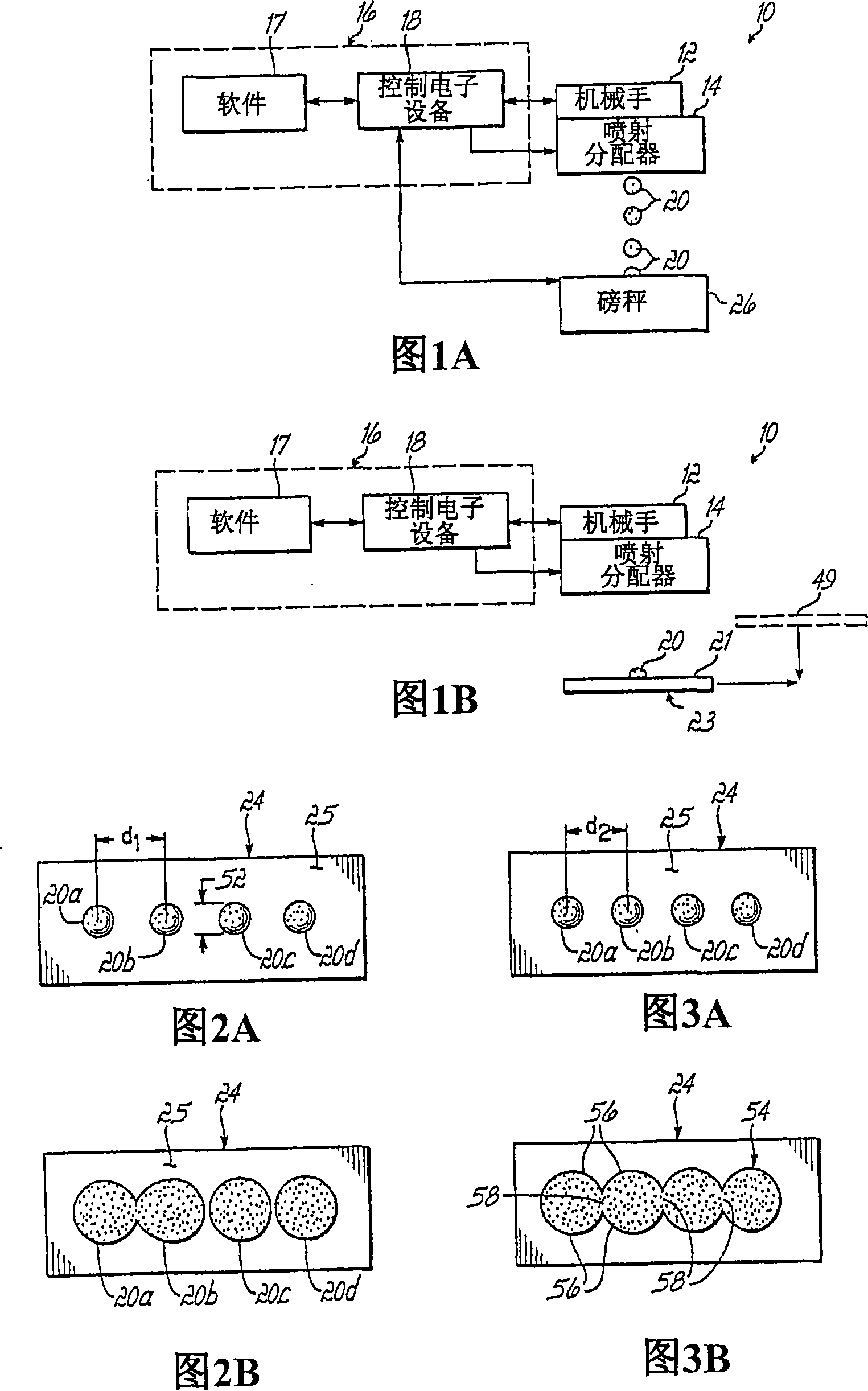
[0060] The results of Example 1 are shown in Figures 2A and 2B. In Example 1, as shown in FIG. 2A, every adjacent pair of points 20 (eg, points 20a and 20b) are spaced apart from each other by a first distance d 1 . distance d 1 About 1.02mm. As shown in Figure 2B, after lamination, points 20b, 20c, and 20d are still spaced apart from each other, while points 20a and 20b are somewhat connected. However, this result was unacceptable since no continuous line of viscous material was formed. Therefore, water and oxygen and other harmful materials can diffuse through the space between points 20b and 20c and between 20c and 20d.

example 2

[0062] The results of Example 2 are shown in Figures 3A and 3B. In Example 2, the spacing between adjacent dots 20 is reduced such that the spacing d between adjacent dots (eg, dots 20a and 20b) shown in FIG. 3A 2About 0.89mm. In this case, after lamination, each point 20a, 20b, 20c and 20d is connected to each other, as shown in FIG. 3B, and forms a continuous line 54 of adhesive material. However, as shown in Figure 3B, the lines 54 do not have a uniform width. Instead, line 54 includes a plurality of sharp corners or arcuate portions 56 , with line 54 having a relatively narrow width, indicated at 58 , extending between opposite sides of line 54 within the intersection regions of adjacent sharp corners 56 . This is also an unacceptable result since the viscous material is used to form the seal, which typically has a square or rectangular shape around the perimeter of the display panel (eg, OLED display panel). This is because water, oxygen, and harmful substances can pas...

example 3

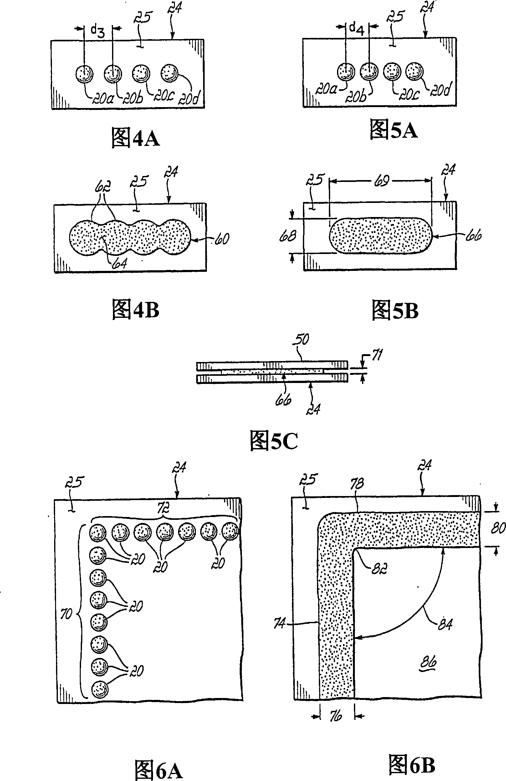
[0064] The results of Example 3 are shown in Figures 4A and 4B. In Example 3, as shown in FIG. 4A, a plurality of points 20a, 20b, 20c, and 20d are formed by another distance d between the centers of adjacent points (such as points 20a and 20b). 3 separated. distance d 3 The value of is about 0.76mm, which is smaller than the spacing d shown in Figures 3A and 2A respectively 2 and d 1 . FIG. 4B shows the adhesive material on the surface 25 of the substrate 24 after the lamination process, and shows the dots 20 a , 20 b , 20 c , and 20 d connected to each other to form a continuous line 60 . Line 60 has a more uniform width than line 54 shown in FIG. 3B , but is still unacceptably wavy, as shown by sharp corners 62 on line 60 . Sharp corner 62 creates a region of reduced width, such as region 64 , on line 60 . These areas of reduced width have an adverse effect on the sealing ability of the adhesive material.


PUM


Abstract

A method is provided for forming at least one continuous line of viscous material between two components of an electronic assembly forming two substrates. The method includes the steps of depositing a plurality of spaced apart dots of the viscous material onto a surface of a first one of the substrates and bringing a second one of the substrates into contact with the dots causing the dots to merge together to form at least one continuous line of the viscous material between the two substrates.

Description

[0001] cross reference [0002] This application claims priority to U.S. Provisional Patent Application No. 60 / 696,386, "METHOD OF FORMING AT LEAST ONE CONTINUOUS LINE OF VISCOUS MATERIAL BETWEEN TWOCOMPONENTS OF AN ELECTRONIC ASSEMBLY," filed July 1, 2005, the entire contents of which are incorporated by reference into this article. technical field [0003] The present invention relates to a method of applying an adhesive material between two parts of an electronic assembly. Background technique [0004] During the manufacture of electronic components Organic Light Emitting Diode (OLED) display panels, it is necessary to dispense one or more rectangular shaped small amounts of adhesive material such as ultraviolet (UV) curable resin on a glass substrate and then place a second substrate on top of the resin such that The resin forms a seal between the two glass substrates. The seal between the substrates must limit the diffusion of oxygen, water or other harmful substances...

Claims


Application Information

Patent Timeline
IPC IPC(8): H01L51/52
Inventor 阿莱克斯・J・巴比亚尔兹克里斯蒂娜・巴比亚尔兹方良伟埃里克・菲斯克克里斯托弗・L・朱斯蒂霍拉蒂奥・基尼奥内斯弗洛里安娜・苏里亚维查亚托马斯・L・拉特里格
Owner NORDSON CORP
Why Eureka
Try Eureka