Automatically adjusting self-tightening wrench

a self-adjusting, wrench technology, applied in the direction of wrenches, screwdrivers, manufacturing tools, etc., can solve the problems of constant aggravating for users, “knuckle busters”, etc., to facilitate frictional engagement of users, easy use, and easy thumb release

Inactive Publication Date: 2005-12-06
WEI CHEN
View PDF24 Cites 18 Cited by
  • Summary
  • Abstract
  • Description
  • Claims
  • Application Information

AI Technical Summary

Benefits of technology

[0006]The gripping surface area of the jaw member at an angle substantially normal to the center axis of the elongated handle when the jaw member is in a fully biased position rotated to its closest point to the work surface formed on the end of the handle. The handle gripping surface is formed on a working face portion shaped like an arc. When the jaw member rotates about the axle, the jaw gripping surface area of the jaw member becomes increasingly distant from the handle gripping surface formed on the arced face of the handle because both circles have different center points. This increase in distance allows the device to accommodate larger and larger objects between the jaw gripping surface and the handle gripping surface as the jaw member is rotated to increase the distance of the planar face of the jaw member and the jaw gripping surface thereon, away from the handle gripping surface on the handle face.
[0015]It is yet another object of this invention to provide a self adjusting wrench which by using a curved gripping surface on the handle and planar surface on the jaw maintains a substantially parallel engagement upon the object being turned by the wrench and substantially equal imparting of force by each working face upon the object turned.

Problems solved by technology

Consequently, because the adjustable wrench was not sized to the object being worked on, slippage occurred of the wrench on the object being turned resulting in a “knuckle buster” which has been a constant source of aggravation to the user of such wrenches.
Further, such adjustable wrenches generally require some movement of an adjusting mechanism by the user which requires two hands and a reasonable high amount of dexterity.

Method used


Image

  • Automatically adjusting self-tightening wrench
  • Automatically adjusting self-tightening wrench

Examples


Embodiment Construction

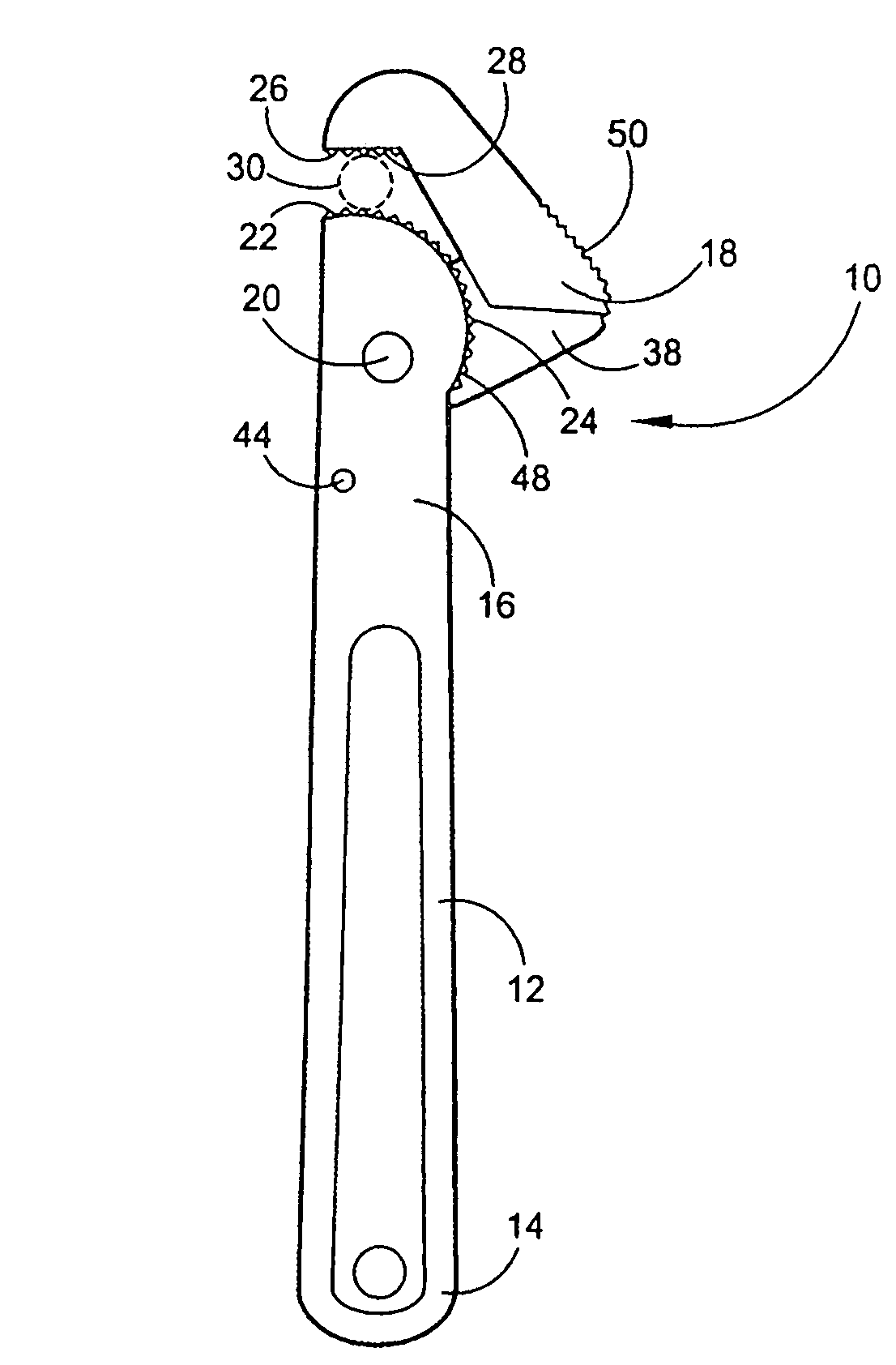
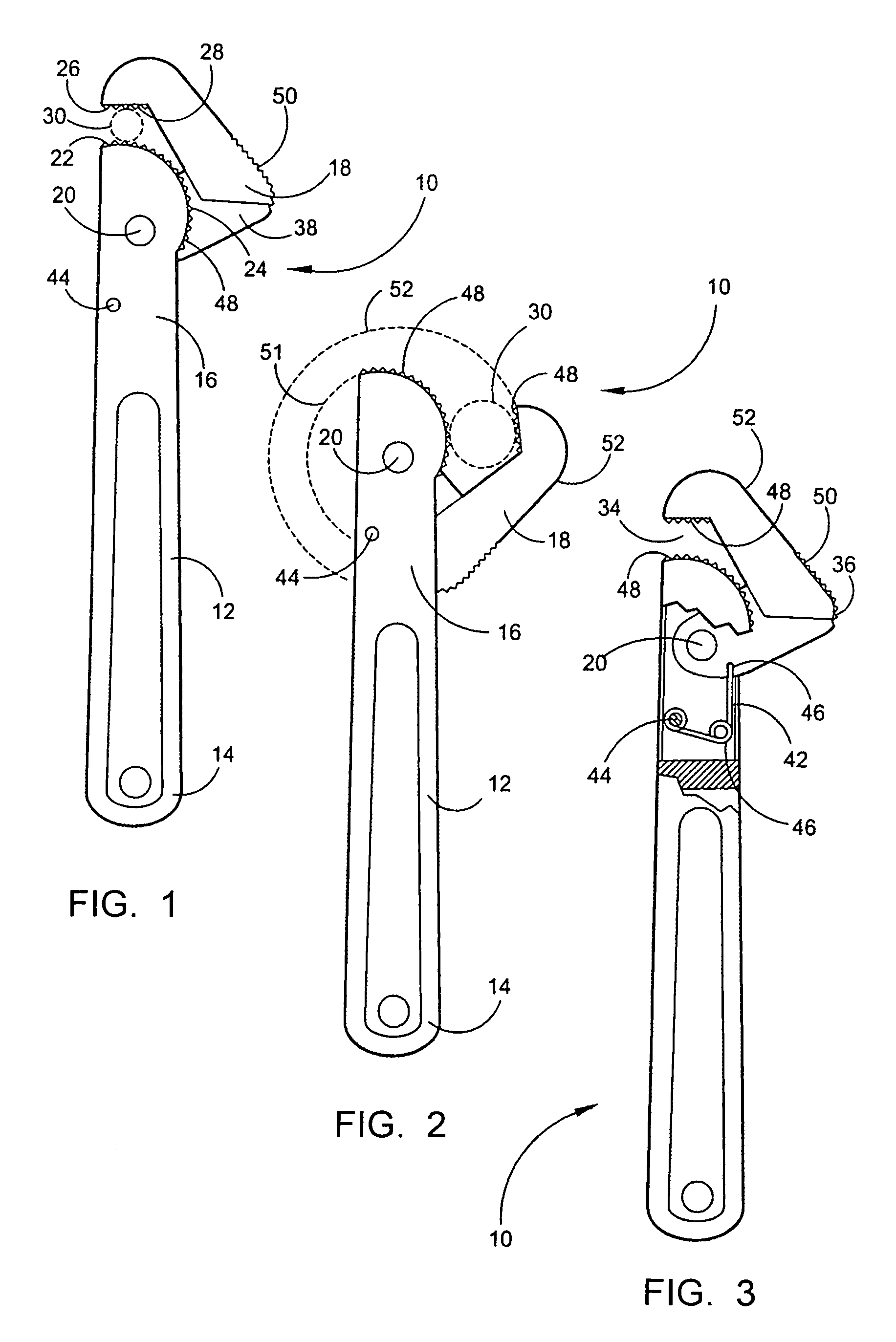
[0021]FIGS. 1–3 preferred embodiments of the disclosed device 10 with FIG. 1 depicting a side view of the disclosed self adjusting wrench device 10. The device 10 features a handle 12 having a grasping end 14 and a working end opposite the grasping end 14.

[0022]A rotatingly mounted jaw member 18 is mounted to the handle 12 at th working end 16 using a pin 20 or axle which communicates into the handle 12 and jaw member 18 and attaches the jaw member 18 in rotational engagement with the handle 12 about the working end 16 of the handle 12.

[0023]On the working end 16 of the handle 12 arc shaped handle working face 22 is formed and on this handle working face 22 a handle gripping surface 24 is formed. The current best mode of the device 10 features the handle working surface 22 in an arc and forming the jaw gripping surface 26 on a generally planar face 28 of the jaw member 18 opposite the handle working face 22. By forming the jaw gripping surface 26 on a substantially planar jaw planar...


PUM


Abstract

A self-adjusting wrench having a handle and a jaw member rotationally attached thereto. A smoothly curved handle face opposes a planar face on the jaw member which adjusts for distance from the curved handle face by following a generally circular path around a pinned attachment of the jaw member to the handle. A spring or similar biasing device continuously urges the jaw member toward the handle thereby making the device self adjusting to the size of the object placed between the jaw member and the curved handle surface.

Description

FIELD OF THE INVENTION[0001]The disclosed device relates to a self adjusting self tightening wrench. More particularly it relates to a wrench with a handle and rotationally pivoting jaw member which form a substantially parallel grip on objects throughout the range of rotation of the jaw member which will accommodate an infinite number of sizes of objects to be rotated by the wrench between the wrench's minimum and maximum mouth openings.BACKGROUND OF THE INVENTION[0002]Adjustable wrenches in the past have generally been of a type which laterally translates a moveable jaw member away from and toward and fixed working surface on the wrench handle. By translating the jaw member further away, using a geared mechanism, the distance between the fixed working surface on the handle and the moveable working surface of the jaw member may be increased to a finite distance. This allows such adjustable wrenches to accommodate a range of sizes of bolts, pipes, nuts, or other objects needing rota...

Claims


Application Information

Patent Timeline
Patent Type & Authority Patents(United States)
IPC IPC(8): B25B13/28B25B13/50
CPCB25B13/28B25B13/505
Inventor WEI, CHEN
Owner WEI CHEN
Why Eureka
Try Eureka