Direct-acting electric operated valve

a technology of electric operated valves and valve stands, which is applied in the direction of valves, operating means/releasing devices, valves, etc., can solve the problems of troublesome wiring operation from a valve stand to the solenoid valve, increased construction cost and maintenance cost of copper pipes and solenoid valves, and reduced air venting

Inactive Publication Date: 2005-12-06
ICHIMARU GIKEN
View PDF7 Cites 23 Cited by
  • Summary
  • Abstract
  • Description
  • Claims
  • Application Information

AI Technical Summary

Benefits of technology

[0015]At that time, the eccentric cam can be retained at an upper retaining position which is slightly exceeding a top dead center and at a lower retaining position which is slightly exceeding a bottom dead center. Therefore, it is possible to limit the reverse rotation of the eccentric cam, the members can be held in their positions, and the closed state of the valve opening by the valve body can be maintained.
[0042]Thereupon, if the coil spring is restrained by the upper spring seat, the lower spring seats the spring shaft (cylinder body) and the spring case (stem), and the coil spring is previously compressed and mounted, the biasing force for maintaining the closed state of the valve opening by the valve body can be obtained by additionally compressing the spring with short stroke from the compressed state. Thus, it is possible to make the vale compact by shortening the stroke, and to reduce the energy required for compressing the spring.

Problems solved by technology

According to the conventional piston valve, however, construction cost and maintenance cost are required for the copper pipe and solenoid valve, and if the number of valves is increased, wiring operation from a valve stand to the solenoid valve is troublesome.
There is also a problem that when power supply is stopped, there is danger that air is vent and the piston is returned by a spring.

Method used


Image

  • Direct-acting electric operated valve
  • Direct-acting electric operated valve
  • Direct-acting electric operated valve

Examples


first embodiment

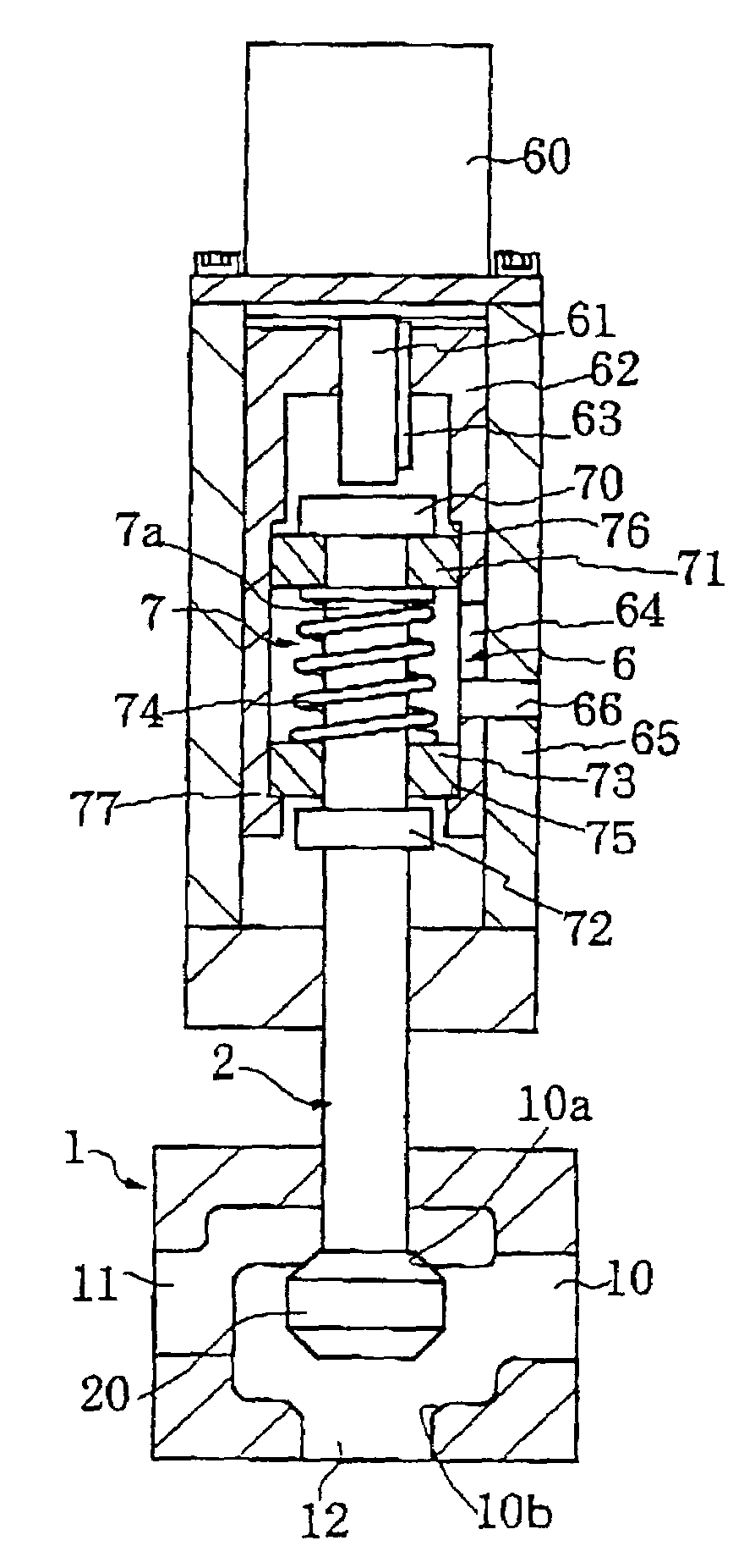
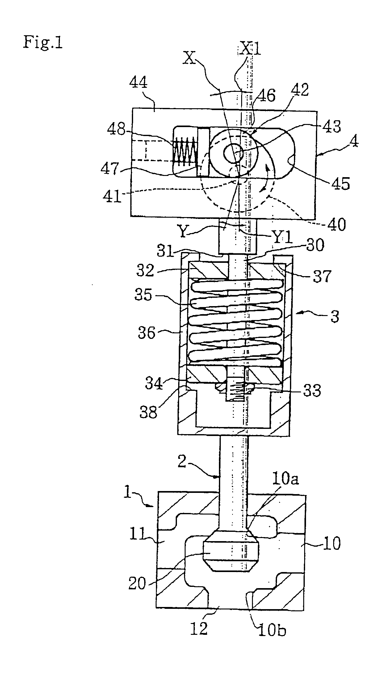
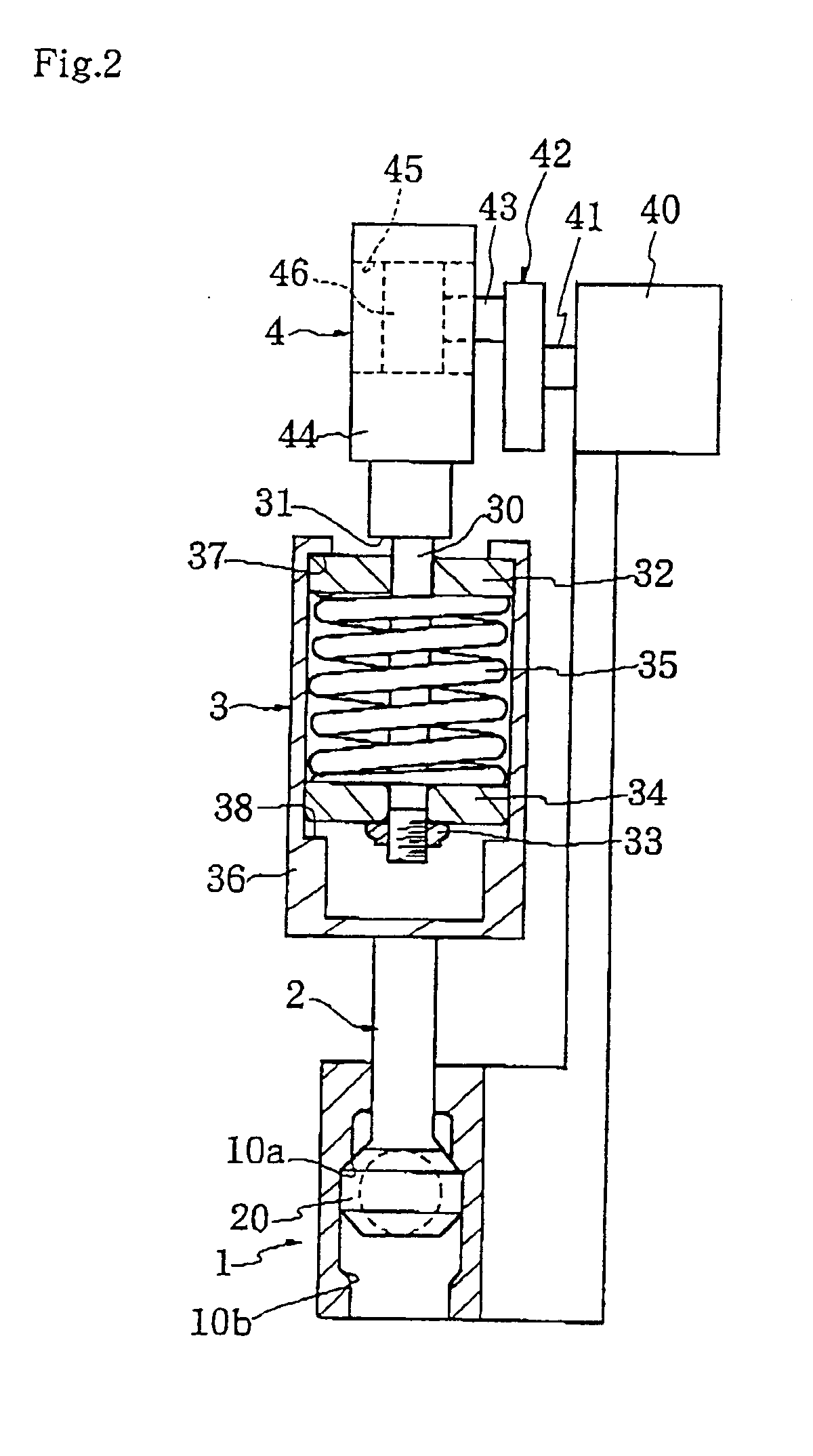
[0052]FIG. 1 is a front sectional view of a direct-acting electric operated valve according to the present invention. FIG. 2 is a side sectional view of the direct-acting electric operated valve. FIG. 3 is an explanatory view of operation of the direct-acting electric operated valve.

[0053]In the drawings, a reference number represents a valve body. Formed in the valve body 1 are a main passage 10, a first passage 11 which is in communication with the main passage 10 through a first valve opening 10a, and a second passage 12 which is in communication with the main passage 10 through a second valve opening 10b.

[0054]When a stem 2 vertically reciprocates, a valve body 20 vertically reciprocates between the first valve opening 10a and the second valve opening 10b. In this case, this direct-acting electric operated valve can switch passages such that if the stem 2 moves upward and the first valve opening 1a is closed with the valve body 20, the main passage 10 and the second passage 12 ...

second embodiment

[0070]Next, FIG. 4 is a side sectional view of a direct-acting electric operated valve according to the invention.

[0071]This direct-acting electric operated valve has position sensor 51 and 52 for detecting the top dead center X1 and the bottom dead center Y1 of the eccentric cam (rotor) 42 which rotary reciprocates by an electric motor 50. The position sensor 51 and 52 detect the reciprocating end of the eccentric cam 42, and the electric motor 50 is stopped by signals from the position sensor 51 and 52.

[0072]Therefore, if the eccentric cam 42 reaches near the top dead center X1 and the bottom dead center Y1, the electric motor 50 is stopped by the signals from the position sensor 51 and 52 and thereafter, the eccentric cam 42 reaches the reciprocating end by the inertia force and the spring force. Thus, it is possible to prevent the motor driving system from being damaged while precisely stopping the electric motor 50 at the reciprocating end position of the eccentric cam 42.

[0073...


PUM


Abstract

A direct-acting electric operated valve has a stem which reciprocates by an electric motor without using air pressure.In this direct-acting electric operated valve, as the stem 2 vertically reciprocates, a first passage 11 and a second passage 12 are switched over. A cam mechanism 4 is formed for converting rotary reciprocating motion of an eccentric cam 42 which rotary reciprocates by an electric motor 40 into vertical reciprocating motion. The eccentric cam is retained at an upper retaining position X which is slightly exceeding a top dead center X1 and at a lower retaining position Y which is slightly exceeding a bottom dead center Y1. In a state in which an integral coil spring 35 which is previously held between an upper spring seat 32 and a lower spring seat 34 in its compressed state is mounted to a spring shaft 30 which extends from a cam mechanism, the coil spring 35 is accommodated in a spring case 36 connected to the stem.

Description

TECHNICAL FIELD[0001]In a direct-acting valve which is opened and closed by reciprocating motion of a stem, the present invention relates to a direct-acting electric operated valve using an electric motor as driving means of the stem.BACKGROUND ART[0002]In a conventional direct-acting valve of this kind, an air cylinder is used as driving means of a stem. In an air driving type piston valve, air pressure is used for driving the valve, an air pipe (usually copper pipe) is required up to a valve body, and since a piston section is driven by ON / OFF operation of the air pressure, a solenoid valve is provided separately from the air pipe to switch an original pressure and an atmospheric pressure, thereby opening and closing the valve body.[0003]According to the conventional piston valve, however, construction cost and maintenance cost are required for the copper pipe and solenoid valve, and if the number of valves is increased, wiring operation from a valve stand to the solenoid valve is...

Claims


Application Information

Patent Timeline
Patent Type & Authority Patents(United States)
IPC IPC(8): F16K11/044F16K31/04F16K31/524F16K31/528
CPCF16K11/044F16K31/04F16K31/52416F16K31/528F16K31/047Y10T74/18296Y10T137/86686
Inventor ICHIMARU, HIRONOBU
Owner ICHIMARU GIKEN
Why Eureka
Try Eureka