Seismic isolation bearing

a technology of seismic isolation bearing and bearing plate, which is applied in the direction of bridges, mechanical equipment, bridge structural details, etc., can solve the problems of dangerous displacement, inefficient space utilization of seismic isolation bearings of this type, and large upper portions, so as to achieve the effect of dissipation of energy

Inactive Publication Date: 2005-12-06
LEE GEORGE C +2
View PDF19 Cites 24 Cited by
  • Summary
  • Abstract
  • Description
  • Claims
  • Application Information

AI Technical Summary

Benefits of technology

[0027]Another embodiment of the isolation bearing provides for both X and Y isolation by employing an intermediate plate between the upper and lower plates, a lower roller between the lower and intermediate plates for X axis isolation, and an upper roller between the intermediate and upper plates for Y axis isolation. This two layer isolation bearing allows for different restoring forces and different friction forces to be implemented with respect to the X and Y isolation axes, as dictated by design considerations.
[0028]Yet another embodiment of the present invention provides both X and Y isolation in a single layer design by employing a spherical roller between pyramid-like surfaces of a lower plate and / or an upper plate, wherein deformation of the spherical roller and rolling friction help to dissipate energy.

Problems solved by technology

A recognized drawback of these bearings is that they must be very tall to allow for seismically induced lateral displacements of one to two feet.
Sliding isolation bearings of this type are space-inefficient because the concave surface of the upper portion must be large enough to accommodate horizontal movement in all directions, thus making the upper portion unduly large.
This can be a significant disadvantage where space restrictions apply, such as with a highway overpass bridge where the bridge pier is of limited width dictated by the traversed lanes of highway.
It has also been recognized that the resonant frequency of the oscillatory sliding bearing could be matched by the earthquake, leading to dangerous displacements.
Another disadvantage is apparent after an earthquake has occurred: displacement is permanent, and hydraulic jacks are required to return the displaced structure to its original position, if this is possible.
While this arrangement is efficient in its use of space for a two-axis isolation system and is effective in reducing the absolute acceleration of the superstructure which it supports, it is less than optimal as a solution for bridge isolation, as compared to building isolation.
However, the problem of bridge isolation is much more complex.
WO 01 / 42593 are designed to have the same performance characteristics along the X axis as they do along the Y axis, making it difficult to realize the goals of bridge isolation.
Another problem not solved by the embodiments shown in WO 01 / 42593 relates to stability of the bearing in the event of normal light horizontal loads, such as wind, traffic, etc.
The isolation bearings described in WO 01 / 42593, and many other prior art isolation bearings for that matter, are not adequately designed with respect to the reduction of large bearing displacement, a factor that is especially important for bridge isolation.
The first reason is a built-in problem of conventional linear (or slightly non-linear) bearings: the phase of the motion of the superstructure is nearly opposite to the phase of the ground motion.
The second reason is that many bearing designs cannot avoid a special overlarge displacement due to motion instability and related sub-instability in the vibrational system.
Finally, another factor that renders prior art bearings less than optimal for use in bridge isolation is that bridge isolation may use a considerably shorter period than building isolation.

Method used


Image

  • Seismic isolation bearing
  • Seismic isolation bearing
  • Seismic isolation bearing

Examples


second embodiment

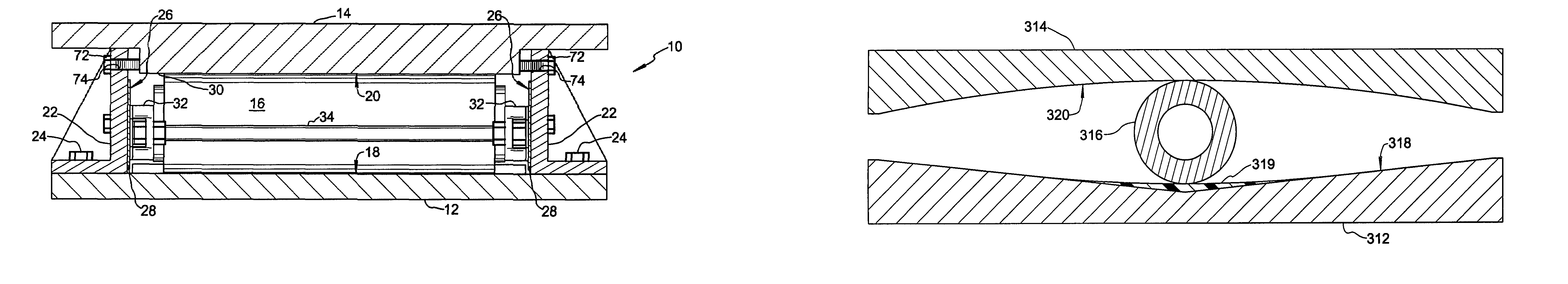
[0085]As mentioned above, certain factors inherent in the structural environment for which the isolation bearing is designed may dictate that different isolation characteristics be present with respect to the X isolation axis as compared with the Y isolation axis. One way this is achieved in isolation bearing 110 of the second embodiment is by providing a different frictional force associated with sliding guides 132 than that associated with sliding guides 133, for example by specifying different friction tracks and friction plates to attain different coefficients of friction for the X and Y isolation axes. Another way this is achieved in isolation bearing 110 is by providing different restoring forces along the X and Y isolation axes through the use of different slope angles for downwardly facing bearing surface 119 and upwardly facing bearing surface 121. This approach offers means for limiting peak bearing displacement, which is substantially inversely proportional to the slope a...

first embodiment

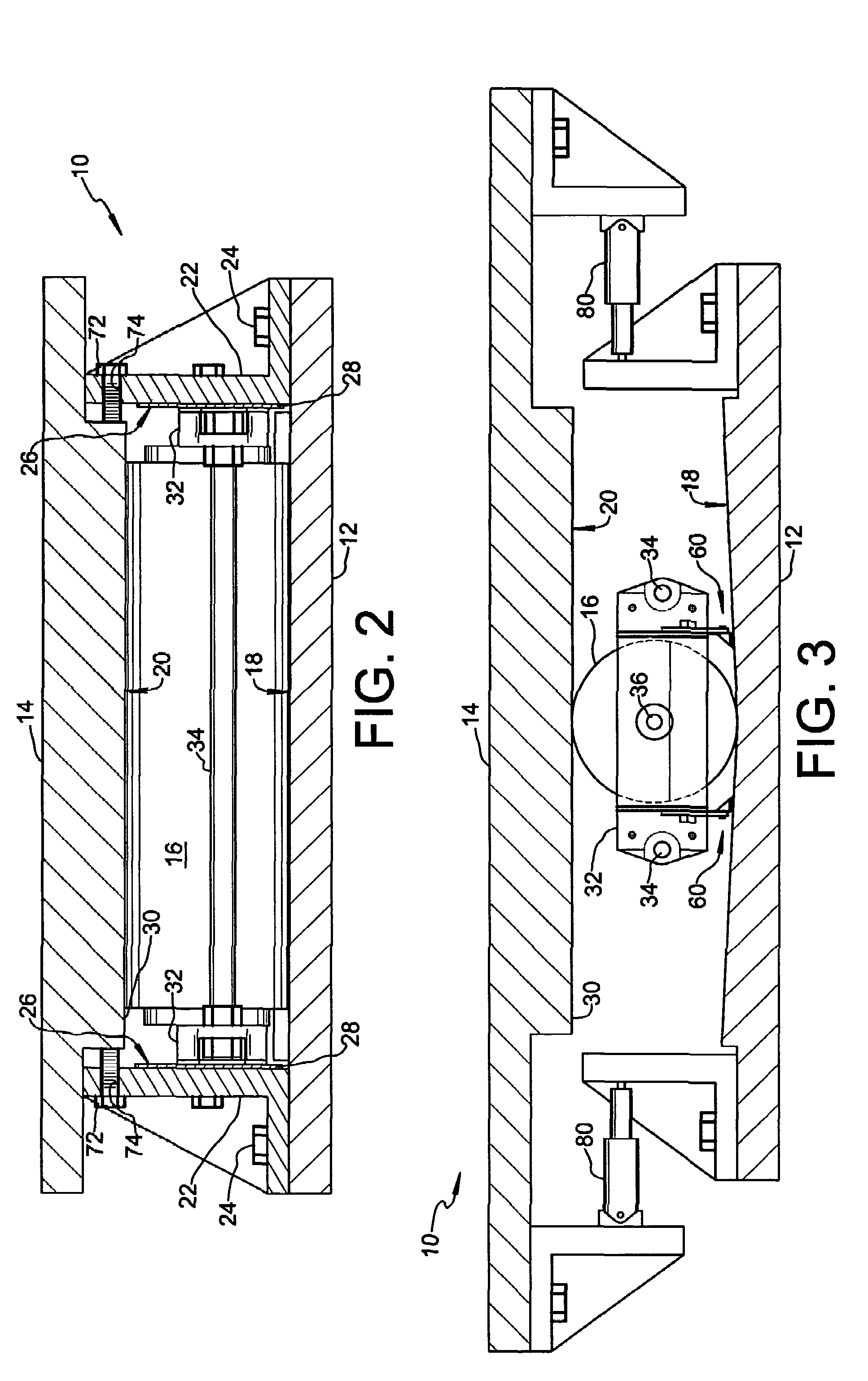
[0086]Damper units (not shown in FIGS. 8 and 9) of different types can be installed between lower plate 112 and intermediate plate 113 to act along (parallel to or coincident with) the X isolation axis, and between intermediate plate 113 and upper plate 114 to act along (parallel to or coincident with) the Y isolation axis. In this regard, reference is made to the description of damper units 80 used in connection with isolation bearing 10 of the

[0087]FIGS. 12 and 13 depict a locking mechanism useful in either isolation bearing 10 of the first embodiment or isolation bearing 110 of the second embodiment as an alternative to bolts 72 described above in connection with isolation bearing 10. In the context of the Y isolation axis of isolation bearing 110, the locking mechanism comprises a first member 140 fixed relative to upper plate 114 and having a pin hole 142 therethrough, a second member 144 fixed relative to intermediate plate 113 and having a travel slot 146 that extends paralle...


PUM


Abstract

A seismic isolation bearing comprises a lower plate, an upper plate, and a cylindrical roller in rolling contact with an upwardly facing, bearing surface of the lower plate and a downwardly facing surface of the upper plate. The lower plate is fixable to a base, while the upper plate is fixable to a superstructure. One or both bearing surfaces are sloped to form a central trough at which the cylindrical roller resides under normal weight of the superstructure, and toward which the roller is biased when displacement between the plates occurs. A pair of sidewall members are fixed to the lower plate to withstand strong forces directed laterally with respect to the isolation axis along which rolling displacement occurs, and a pair of sliding guides carried one at each end of the roller provide dry frictional damping as they engage an inner wall surface of a corresponding sidewall member.

Description

CROSS-REFERENCES TO RELATED APPLICATIONS[0001]The present application claims benefit as a continuation-in-part of application Ser. No. 09 / 994,148 filed Nov. 26, 2001 now abandoned; and the present application claims further benefit as a continuation-in-part of copending application Ser. No. 10 / 455,857 filed Jun. 6, 2003, which itself is a continuation-in-part of the aforementioned application Ser. No. 09 / 994,148 filed Nov. 26, 2001 now abandoned.BACKGROUND OF THE INVENTION[0002]I. Field of the Invention[0003]The present invention relates to devices for isolating structural members from seismic forces to minimize damage and reduce casualties in the event of an earthquake.[0004]II. Description of the Related Art[0005]A known design approach for improving structural response to earthquakes is based on the principle of seismic isolation, wherein energy is generally dissipated by mechanical dissipating devices such as lead cores within lead-rubber bearings, by friction in sliding bearing...

Claims


Application Information

Patent Timeline
Patent Type & Authority Patents(United States)
IPC IPC(8): E04HE04H9/02
CPCE04H9/023
Inventor LEE, GEORGE C.LIANG, ZACHNIU, TIE-CHENG
Owner LEE GEORGE C
Why Eureka
Try Eureka