Bearing preload cage assembly

a preload cage and bearing technology, applied in the direction of bearings, shafts and bearings, rotary bearings, etc., can solve the problems of individual bearings not being able to tolerate thrust loads, accelerated wear or fatigue failure of cages, and damage to bearings

Inactive Publication Date: 2005-12-06
VEZINA MARTIN J
View PDF10 Cites 51 Cited by
  • Summary
  • Abstract
  • Description
  • Claims
  • Application Information

AI Technical Summary

Benefits of technology

[0036]The unique advantage of the preload cage concept is that it allows the bearings to be mounted in a back to back configuration that will not allow damaging movements of the unloaded bearing when shaft axial loads exceed spring force. Preload cages allow the precise application of a specific minimum load to the bearings while permitting each bearing to support axial shaft loads to it's rated capacity. Bearing loads imposed by the elastic elements in this configuration are counteracted by shaft axial loads. Because of this, these spring loads are not additive to the shaft loads and they do not de-rate the overall load capacity of the bearings. In addition, these cages allow relatively simple assembly and can be configured with provision to facilitate adjustment of bearing assembly end play through shimming of one of the bearing housing end covers.
[0037]Accordingly, a primary feature of the present invention is the provision of a compact paired bearing mount, particularly for those bearings which must operate at medium to high speeds under changing load conditions.
[0045]Still another feature of the invention is the provision of such a bearing preload cage assembly according to which the first cage segment has an annular mounting flange fixed to the inboard bearing end cover for preventing rotation of the first and second cage segments relative to the bearing housing.

Problems solved by technology

In general however, these individual bearings cannot tolerate a thrust load that is opposite its design load direction.
Factors such as this are entirely dependent upon the initial machining and subsequent maintenance operations on the components and cannot be precisely anticipated by the designer.
This skidding can rupture the lubricant film and result in damaging wear to the bearing.
In tapered roller bearing applications, where the orientation of the rolling elements is maintained by the internal bearing cage, excess clearance can result in accelerated wear or fatigue failure of the cage.
Because of the precise tolerances involved in paired bearing mounting however, the optimum preload is difficult to achieve.
In addition, thermal expansion of the shaft and bearing components during operation will affect preload as well as centrifugal loads in extremely high speed applications.
Because of these uncertainties, the primary risk associated with this method of preloading is the possibility that the resulting bearing load will be greater than desired and result in accelerated wear or catastrophic failure of the assembly.
Because of the load path through the rolling elements in a face to face configuration however, this orientation is generally less stable than a back to back configuration and is unsuitable for many applications.
The converging load paths of the face to face arrangement create a much narrower load base that is less capable of supporting the radial moments generated by shaft unbalance or misalignment.
By virtue of the inherent loading through paired bearings in a conventional back to back configuration, the use of elastic elements between the outer bearing races would defeat the supporting characteristics of the bearing pair.
This would allow catastrophic movement of the unloaded bearing against its design load direction.
While the Bouzakis et al. bearing mount provides an effective means of limiting bearing assembly end play, the elastic elements will have virtually no effect on rolling element loading when mounted in a back-to-back configuration.
In this arrangement, application would be limited to those configurations that will permit the assembly sequence necessary to install a fixed sleeve in the bearing housing between the two bearings with their required interference fits.
The inboard bearing, however, is supported ultimately by springs and, in this configuration, excessive loading in the outboard direction will collapse the springs and allow the shaft to move axially toward the outboard bearing.
This will separate the races of the outboard bearing and result in a catastrophic bearing failure.
This will result in an arrangement that will not support radial forces with respect to the longitudinal axis of the shaft.
In this configuration, excessive loading in the inboard direction will allow the shaft to slide axially through the inner race of the inboard bearing and collapse the springs, separating the races of the outboard bearing and resulting in catastrophic bearing failure.
Because there are no springs between an end cover and it's adjacent bearing, excess axial loading in the direction away from the end cover will collapse springs between the bearings and allow the races of the adjacent bearing to separate, causing catastrophic failure.
Again, however, while the Cameron construction provided a significant improvement to the state of the art at the time it was conceived, problems remain.
Specifically, application of this configuration is also limited to those arrangements that will permit the assembly sequence necessary to install the fixed sleeve in the bearing housing between the two bearings with their required interference fits.
In addition to the apparent difficulty with the assembly of such an arrangement, this configuration has no provision for adjustment of the bearing assembly end play beyond the machining of the spacer.

Method used


Image

  • Bearing preload cage assembly
  • Bearing preload cage assembly
  • Bearing preload cage assembly

Examples


Embodiment Construction

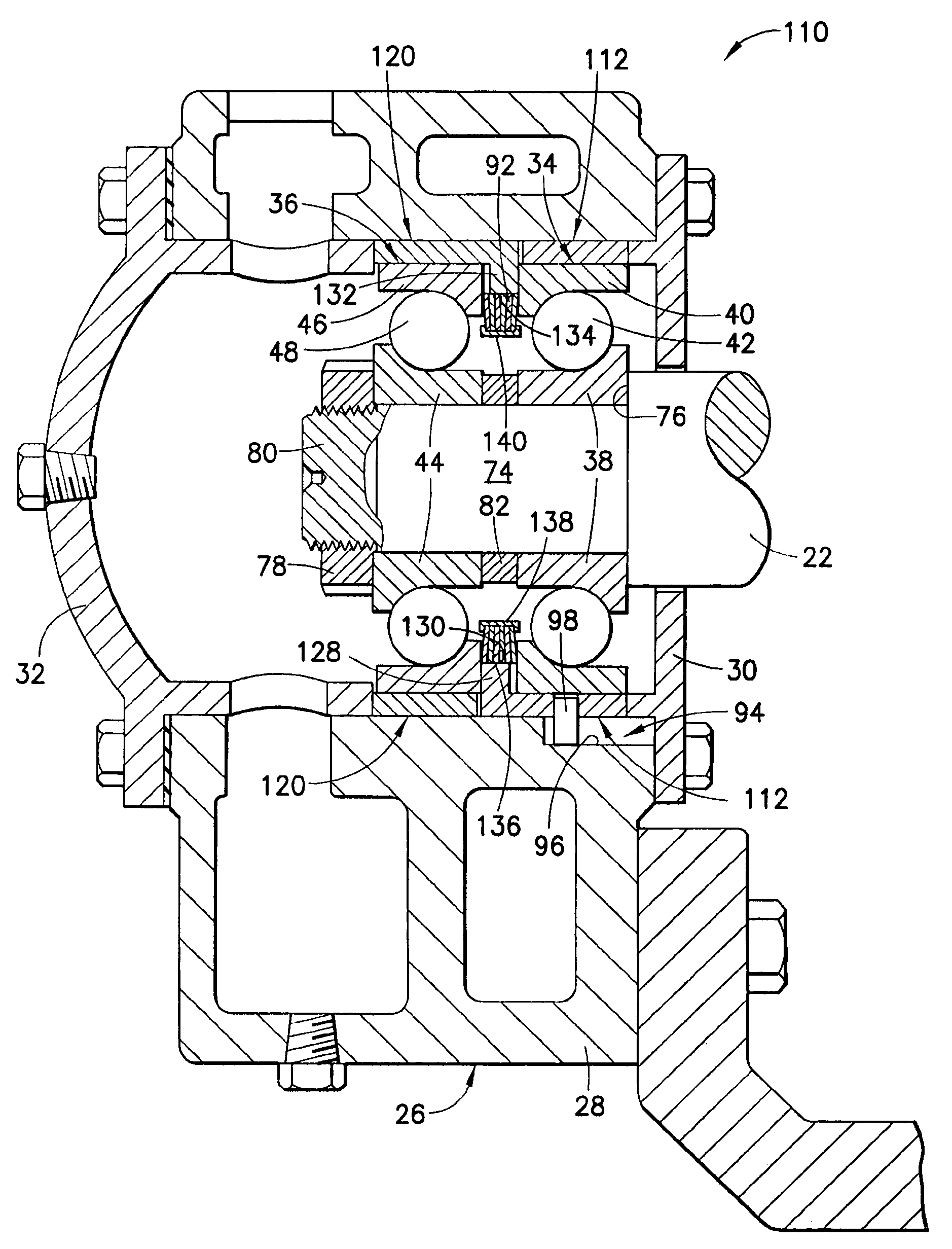
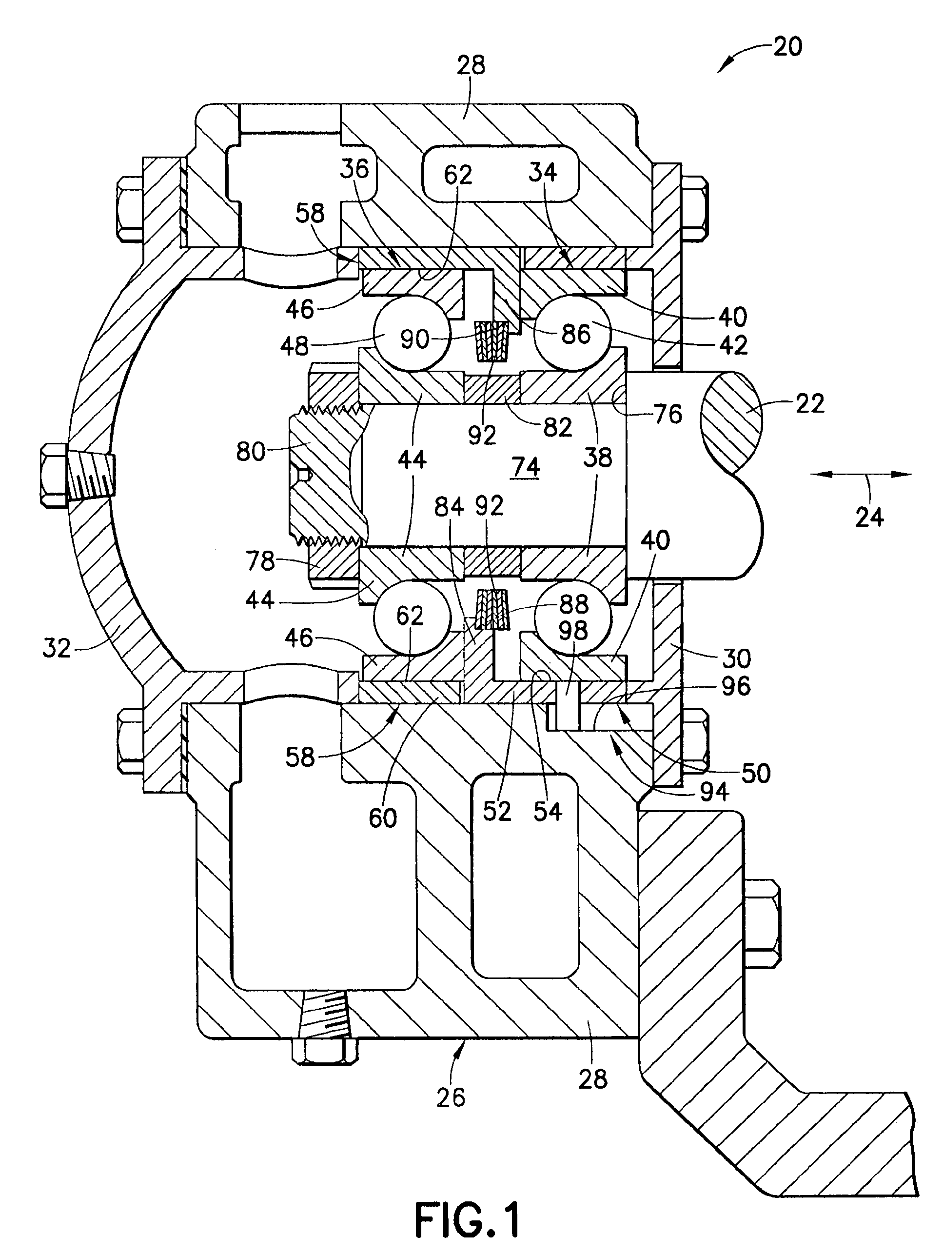
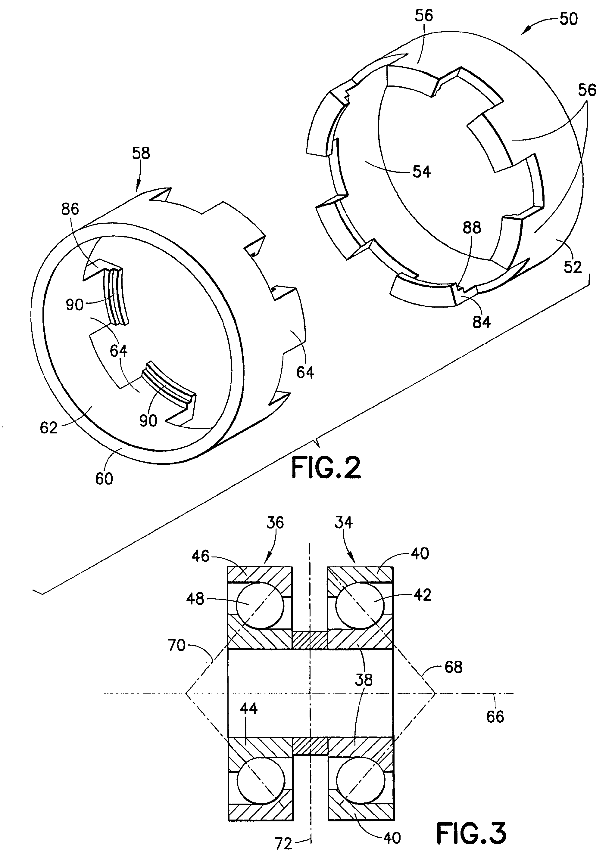
[0057]Turn now to the drawings and, initially, to FIG. 1 in which is shown, diagrammatically, an elevation cross section view of a bearing preload cage assembly 20, incorporating features of the present invention, for rotatably supporting one end of a shaft 22 subject to axial loading as depicted by a double-headed arrow 24. Although the present invention will be described with reference to the embodiments shown in the drawings, it should be understood that the present invention can be embodied in many alternate forms or embodiments. In addition, any suitable size, shape or type of elements or materials consistent with the invention could be used.

[0058]The bearing preload cage assembly 20 includes a bearing housing 26 including a main housing member 28, a first supporting member 30 which is, in actuality, an inboard bearing end cover fixed to the main housing member, and a second supporting member 32 which is, in actuality, an outboard bearing end cover fixed to the main housing mem...


PUM


Abstract

A bearing preload cage assembly for rotatably supporting an axially loaded shaft includes a bearing housing including stationary axially opposed supporting members, first and second axially spaced bearings, each including inner and outer races and rolling elements, first and second cylindrical cage segments coaxial with the shaft, each including a sleeve and circumferentially spaced axially protruding castellations, the outer races engageably received on an internal surface of their associated sleeve, the castellations of each cage segment proximate to and engageable with the outer race of the adjacent bearing, the supporting members proximate to and engageable with an adjacent cage segment, a resilient member biasing at least one of the outer races into full engagement with its rolling elements and, in turn, its rolling elements into full engagement with their inner race whereby the rolling elements of both bearings are maintained in full engagement with their inner and outer races continuously during shaft rotation.

Description

BACKGROUND OF THE INVENTION[0001]1. Field of the Invention[0002]The present invention relates generally to paired configurations of rolling element bearings particularly for those bearings operating at medium to high speeds and subjected to variable loading.[0003]2. Description of the Prior Art[0004]Paired bearings are well known in the art and may be generally described as two duplex bearing assemblies, each having concentric annular inner and outer races which rotate relative to each other, and an annular arrangement of load-supporting rotating elements, such as balls or rollers, located between the races. Angular contact bearings are configured with a radially offset shoulder on at least one of the races. This offset increases the bearings ability to support axial loads in one direction. Applications requiring support for moderate thrust loads in both directions will often incorporate a paired configuration of angular contact rolling element bearings. These bearings, when orienta...

Claims


Application Information

Patent Timeline
Patent Type & Authority Patents(United States)
IPC IPC(8): F16C19/54F16C25/08F16C35/06
CPCF16C19/54F16C25/08F16C35/061F16C19/163F16C19/543F16C25/083F16C35/077
Inventor VEZINA, MARTIN J.
Owner VEZINA MARTIN J
Why Eureka
Try Eureka