Self-locking fastener

a self-locking, fastener technology, applied in the direction of rod connections, screws, coupling device connections, etc., can solve the problems of detracting from the aesthetic appearance of the assembled fence, difficult to hide or conceal the fasteners used, and high labor intensity and time consumption, so as to achieve convenient installation, durable and intact effect of securing structural members, sheet materials and other components

Inactive Publication Date: 2005-12-06
LMT MERCER GROUP
View PDF30 Cites 63 Cited by
  • Summary
  • Abstract
  • Description
  • Claims
  • Application Information

AI Technical Summary

Benefits of technology

[0005]The present invention is directed generally to a fastener which is adapted for effectively securing structural members, sheet materials, and other components to be secured together with opposing surfaces abutting one another to form a durably intact structure. The fastener of the present invention is readily installed without tools to achieve enhanced convenience and expediency. The fastener of the present invention provides the assembled structure with outstanding strength and durability especially at points of securement. The fastener can be readily adapted to secure members selected from, for example, f...

Problems solved by technology

Such fasteners also make the overall assembly of the fence more expensive, labor intensive and time consuming.
Many of the fasteners used are also difficult to hide or conceal, and often detract from the...

Method used


Image

  • Self-locking fastener
  • Self-locking fastener
  • Self-locking fastener

Examples


third embodiment

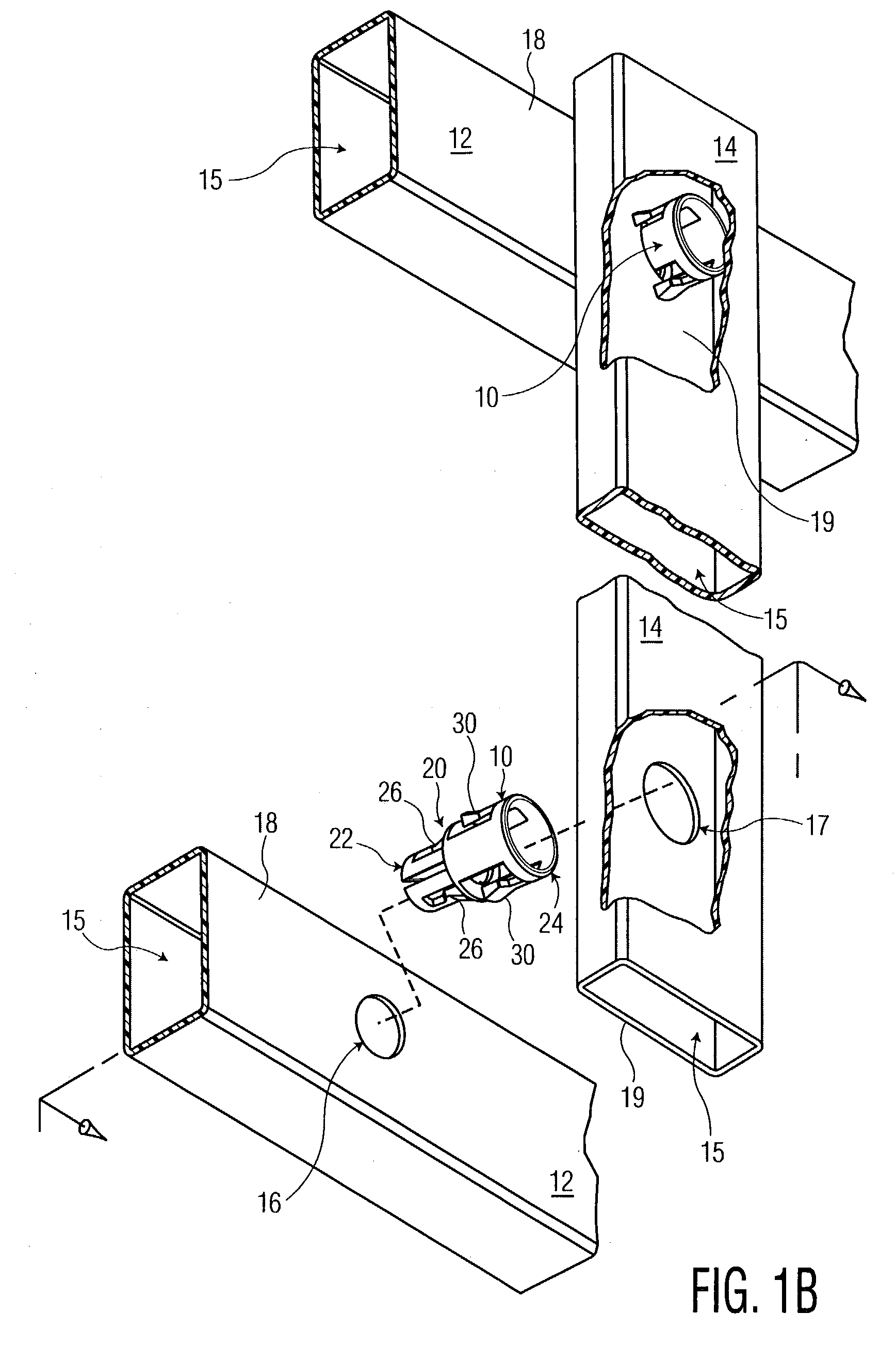
[0054]Referring to FIG. 15, a fastener 100 is shown for the present invention. The free ends 44 and 52 of the first and second arms 26 and 30, respectively, each include stepped portions 102, respectively. The stepped portions 102 are adapted to facilitate the use of the fastener 100 to secure together fence components having varying thicknesses in their respective sidewalls such as sidewalls 18 and 19, shown in FIG. 8, where the first and second arms 26 and 30 are prevented from extending fully into the unloaded position. As shown in FIG. 16, the first and second arms 26 and 30 are able to extend into the unloaded position, and retain the sidewalls 18 and 19, respectively, by the corresponding retaining end surfaces 46 and 54 thereof through pawl-like action. As shown in FIGS. 17 through 19, for progressively greater thicknesses of sidewalls 18 and / or 19, respectively, the first and second arms 26 and 30 are prevented from engaging the respective sidewalls 18 and 19 via the retaini...

fourth embodiment

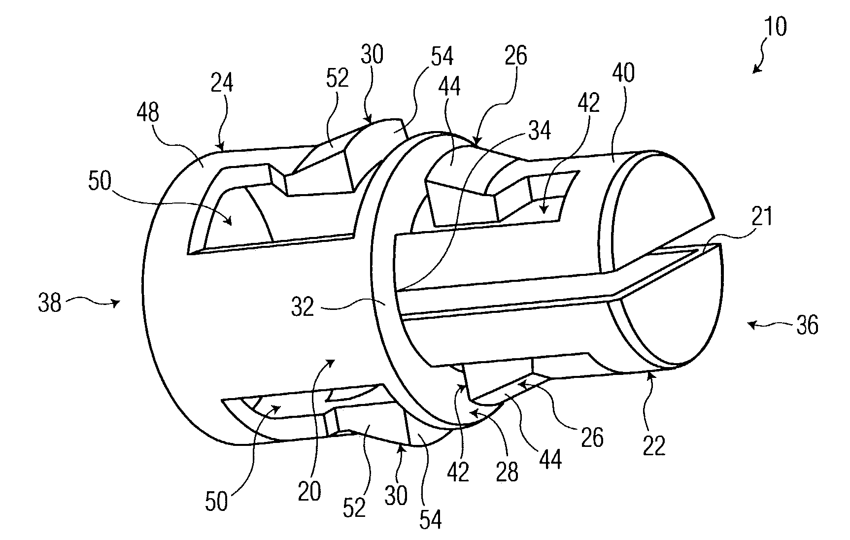
[0055]Referring to FIG. 20, there is shown a fastener 110 for the present invention. The fastener 110 includes all the features of the fastener 10 shown in FIG. 2. The fastener 110 further includes an opening 112 located at the distal end 36 thereof. The opening 112 provides a passage of objects such as wires and the like through the interior cavity 56 from one end to the other.

[0056]Although various embodiments of the invention have been shown and described, they are not meant to be limiting. Those of skill in the art may recognize various modifications to these embodiments, which modifications are meant to be covered by the spirit and scope of the appended claims. For example, a fastener can be provided with the first illustrated embodiment, and further with any one or more of the second through fourth embodiments. Also, a fastener can be provided having the second portion 24 identical to the first portion 22, whereby the flange 28 will provide a stop surface for each portion, but...


PUM


Abstract

A fastener for securing first and second members together at opposing respective flat surfaces thereof, whereby at the point of joining the first member has an aperture concentric with an aperture of the second member, the fastener comprising first and second tubular portions concentric with one another, whereby the second tubular portion is of reduced outside diameter relative to the first tubular portion, a circular flange forming a transverse interior end of the first tubular portion, an interior end of the second tubular portion being rigidly joined to the circular flange, at least one resilient arm being formed in and extending from a sidewall of each one of the first and second tubular portions toward the flange, the at least one resilient arm of each portions each having a free end including a retaining end surface adapted for having close proximity to a side portion surrounding the respective apertures of the first and second members.

Description

FIELD OF THE INVENTION[0001]The present invention relates generally to fasteners, and more particularly to fasteners for securing members such as fence components, printed circuit boards, sheet materials, and so forth, to one another without the use of tools.BACKGROUND OF THE INVENTION[0002]People have used fences through the centuries for marking boundaries and territories, controlling ingress and egress, enhancing privacy and quietude, promoting security and the like. Most fences are typically assembled with the use of conventional fasteners such as nuts and bolts, rivets, clamps, nails, screws, wires and the like. Although such fasteners have been found to be acceptable for securely attaching fence members to one another (e.g., vertical pickets / slats to horizontal rails, or horizontal rails to fence posts), they typically require tools for installation. Such fasteners also make the overall assembly of the fence more expensive, labor intensive and time consuming. Many of the faste...

Claims


Application Information

Patent Timeline
IPC IPC(8): F16B21/08
CPCF16B21/082Y10T403/4674Y10T16/05F16B7/0446F16B2200/40
Inventor FATTORI, JAMES G.LESENSKYJ, ANTHONY J.LESENSKYJ, GEORGE
Owner LMT MERCER GROUP
Why Eureka
Try Eureka