
Waterproof structure of electric junction box

a technology of electric junction boxes and water-proof structures, which is applied in the direction of gaseous cathodes, casings/cabinets/drawers, casings/cabinets/drawers details of electric apparatus, etc., can solve the problems of adversely affecting the waterproof performance of electric junction boxes, and achieve the effect of enhancing the waterproof performan

Active Publication Date: 2005-12-06
YAZAKI CORP
View PDF4 Cites 13 Cited by
  • Summary
  • Abstract
  • Description
  • Claims
  • Application Information

AI Technical Summary

Benefits of technology

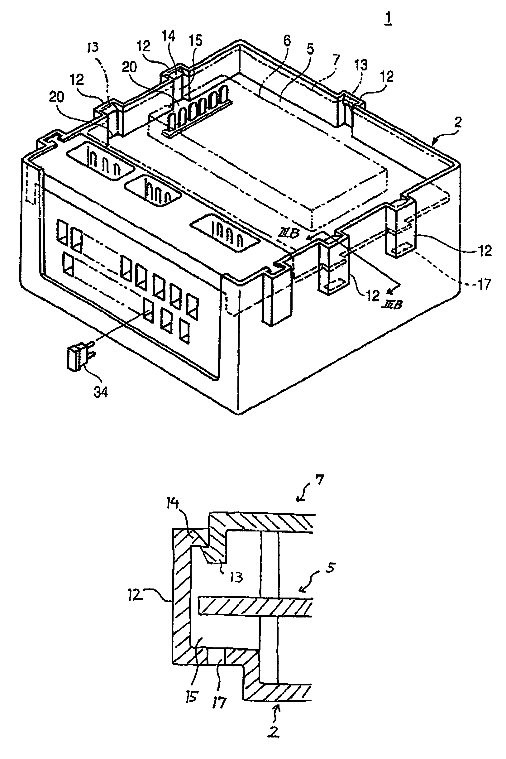
[0008]It is therefore an object of the invention to provide a waterproof structure of an electric junction box in which protruded portions for retaining a cover are formed at a box body, and waterdrops and others are prevented from intruding into the interior of the cover (box body) through the protruded portions, thereby enhancing a waterproof performance.
[0015]In such a configuration, the intrusion of waterdrops along the protruded portion of the first cover body is prevented by the projections of the third cover body. Accordingly, adverse effects, such as short-circuiting and rusting, will not be exercised on electric components disposed within the electric junction box, so that the reliability of the electrical connection of the electric junction box is enhanced over a long time period.
[0016]Further, since the projections of the third cover body also serve as positioning members with respect to the first cover body, the installing operation of the third cover body can be easily and smoothly performed.
[0018]In such a configuration, when the third cover body is installed in the first cover body, each of the projections of the third cover body pushes the retaining projection outwards, so that the protruded portions are accordingly flexed outwards. Therefore, the installing operation of the third cover body is facilitated. When the second cover body is fitted with the first cover body, or when the second and third cover bodies are removed from the first cover body, the same advantages can be attained.

Problems solved by technology

Therefore, waterdrops are more liable to intrude into the protruded portion through the two (right and left) openings, and this encounters a problem that the waterproof performance of the electric junction box is adversely affected.

Method used


Image

  • Waterproof structure of electric junction box
  • Waterproof structure of electric junction box
  • Waterproof structure of electric junction box

Examples


Embodiment Construction

[0027]One preferred embodiment of the present invention will now be described in detail with reference to the accompanying drawings.

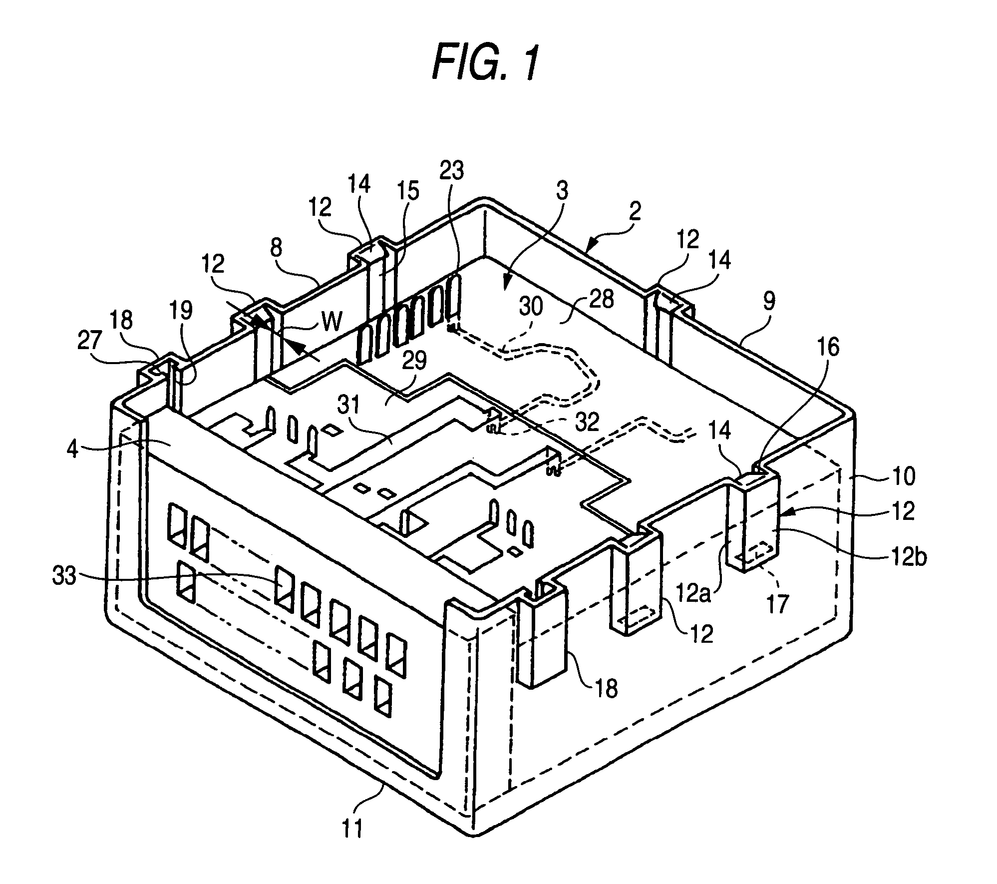
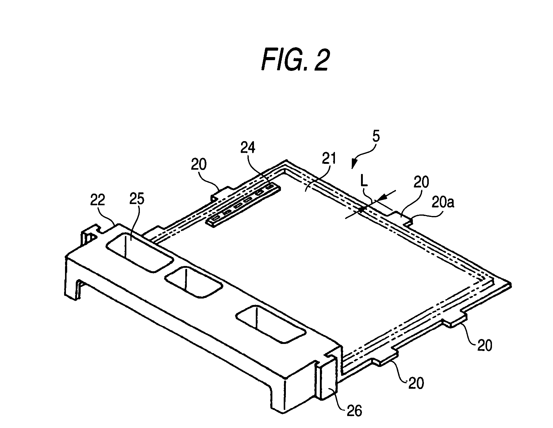
[0028]In this embodiment, an electric junction box 1 comprises: a main cover 2 (box body) molded with synthetic resin; a circuit board assembly 3 and a fuse block 4 which are disposed within the main cover 2; an intermediate cover 5 molded with synthetic resin (see FIGS. 2 and 3A) provided on a sub-assembly formed by the circuit board assembly 3 and the fuse block 4; an electronic control unit 6 (shown in dashed lines in FIG. 3A) mounted on the intermediate cover 5; and a sub cover 7 (shown in dashed lines in FIG. 3A) covering the electronic control unit 6.

[0029]As shown in FIG. 1, the main cover 2 includes a peripheral wall defined by three side walls (left, right and rear walls) 8 to 10, and a base wall 11 perpendicularly connected to lower edges of the side walls 8 to 10. Protruded portions 12 having a rectangular transverse cross-section are formed ...


PUM


Abstract

A first cover body has a first space defined by peripheral walls. Each of a plurality of protruded portions has a through hole, and is outwardly protruded from at least one of the peripheral walls so as to define a groove communicated with the first space and the through hole. Each of a plurality of retainers is provided with one of the protruded portions. A second cover body is fitted with the first cover body so as to close the first space, while being retained by the retainers. A plurality of projections are provided on an outer periphery of a third cover body. The third cover body is disposed in the first space such that each of the projections is fitted into the groove so as to partition the first space from the through hole.

Description

BACKGROUND OF THE INVENTION[0001]This invention relates to a waterproof structure of an electric junction box in which: a circuit board assembly, disposed within a main cover, is covered by an intermediate cover; and a part such as an electronic control unit is mounted on an outer side of the intermediate cover, and is covered with a sub cover.[0002]FIG. 4 shows one form of waterproof structure of a conventional electric junction box disclosed in Japanese Utility Model Publication No. 1-76123U (cf., pages 1–2 and FIG. 2).[0003]This electric junction box 41 includes a first cover 42 and a second cover 43 both of which are made of a synthetic resin, and a circuit board assembly 44 is disposed in a space formed by the two covers 42, 43, and therefore the circuit board assembly 44 is protected from external waterdrops 45, dust and others by the covers 42, 43.[0004]The first cover 42 has retaining projections 47 outwardly extended from a peripheral wall 46 thereof, and the second cover 4...

Claims


Application Information

Patent Timeline
IPC IPC(8): H01R13/52H02G3/08H05K5/02H02G3/14H05K5/03
CPCH02G3/088Y10S439/949
Inventor TAKEUCHI, KUNIHIKOTAKAMATSU, MASAHIROTAKADA, NOBUHIRONOMURA, KOJI
Owner YAZAKI CORP
Learn More