Apparatus and method for electrically and mechanically connecting and disconnecting a power line

a technology of electrical and mechanical connection and power line, applied in the direction of mechanical tension arrangement, connection contact material, coupling device connection, etc., can solve the problems of long delays, severe damage to the service hardware and any structure of the utility company, inconvenience for utility customers, etc., to achieve safe and effective disconnecting of power lines

Inactive Publication Date: 2005-12-06
ELECTRIC POWER RES INST INC
View PDF10 Cites 6 Cited by
  • Summary
  • Abstract
  • Description
  • Claims
  • Application Information

AI Technical Summary

Benefits of technology

[0008]In view of the above, the present invention provides an apparatus and method that safely and effectively disconnects power lines upon the application of a force to the power lines. The disconnection of the power lines is designed to drop the stressed power line to the ground in a controlled fashion. The dropped power line is no longer energized, making it safe for utility company service crew to reconnect the line later. Such a controlled disconnection also reduces the possibility of damage to equipment or structure to which the power lines are attached.
[0009]The present invention also provides an apparatus and method that is cost-efficient to implement since the apparatus is reusable. After the power lines have been disconnected, the utility service crew merely has to reconnect the fallen wires and place the apparatus back together, without making significant repairs to the service hardware or structural components. This design aspect enables quick restoration of power, which reduces cost by limiting downtime and reducing potentially costly service hardware replacement.

Problems solved by technology

Power outages not only inconvenience utility customers but may severely damage the utility company's service hardware and any structure attached to the utility lines, as well as creating a hazard with the possibility of dropping a live electrical wire.
When such damage occurs, it is often costly for the utility company to repair and replace parts but also costly when such damage causes long delays in restoring power service.
This may cause the towers holding such conductors to structurally fail because larger mechanical loads have been imposed upon these towers than intended by their original design.
When the towers do fail, the failure may damage or destroy a number of towers, which may cause long delays in restoring power service.
However, some of these load limiters release the power line prematurely or fail to release the power line after the set amount of force is exceeded.
In addition, once the load limiter releases the power line, the entire device must be replaced since the load limiter is not reusable, which is a costly and time consuming ordeal.
A significant number of power outages, however, occur at the service end of the residential power delivery system, i.e., at the service drop power line from the utility transmission or distribution line to a customer's building.
For example, such outages may be caused by trees or branches falling on the service drop power line connected to the customer's building.
When the tree limb falls on the service drop power line, there is a sudden increase in the tension that may result in damage to the structure and service hardware attached to the building or to the structure and service hardware attached to the utility pole.
For example, tension on a service drop power line may pull the standpipe off of the building roof or side and may structurally damage the roof or side as well.
Further, tension on the service drop power line may cause damage to a transformer located on the service pole.
Moreover, should the service drop power line disconnect from the building, the resulting power line, which could be laying on the ground, may still be energized, thereby causing a potentially dangerous situation.

Method used


Image

  • Apparatus and method for electrically and mechanically connecting and disconnecting a power line
  • Apparatus and method for electrically and mechanically connecting and disconnecting a power line
  • Apparatus and method for electrically and mechanically connecting and disconnecting a power line

Examples


Embodiment Construction

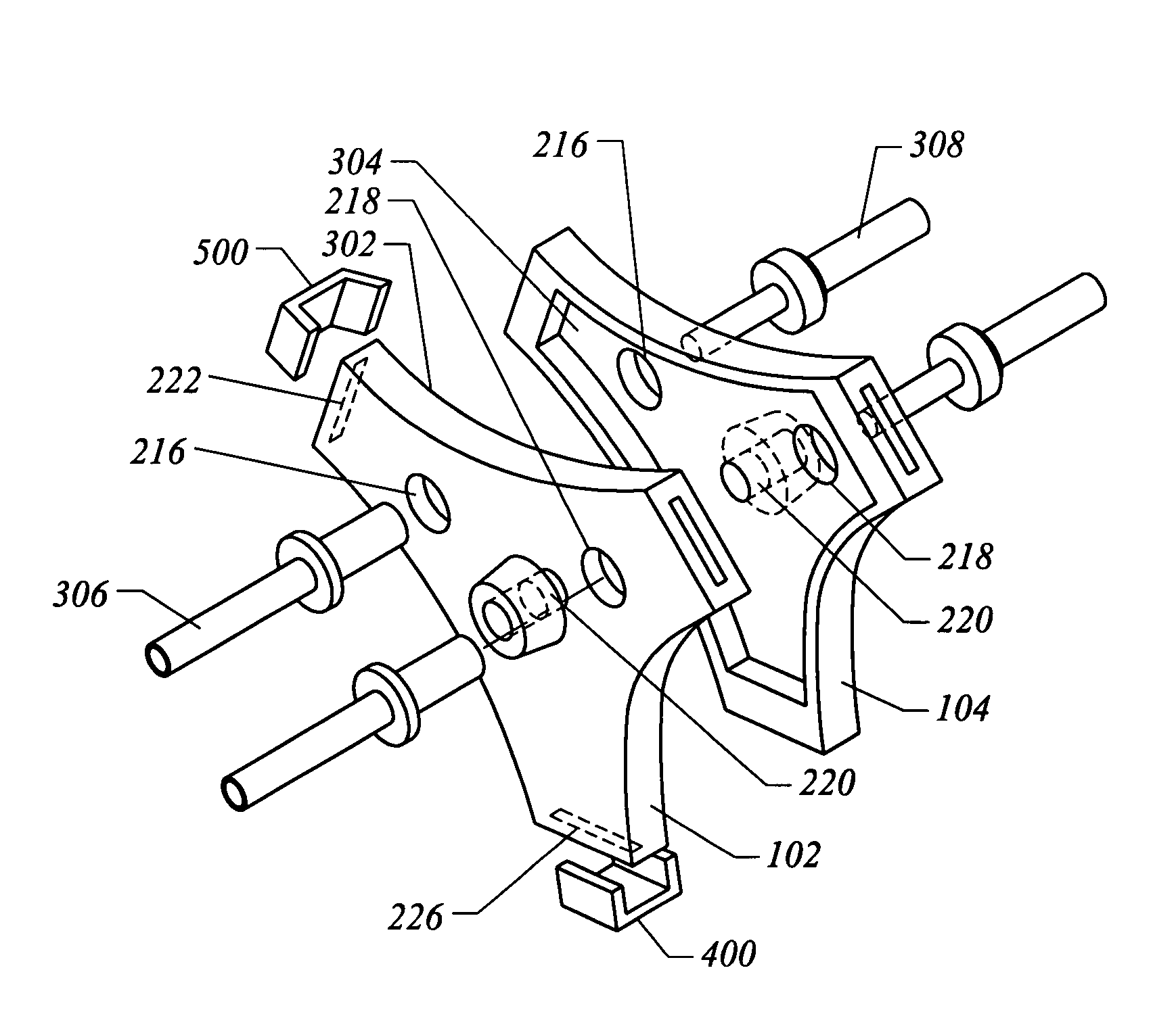
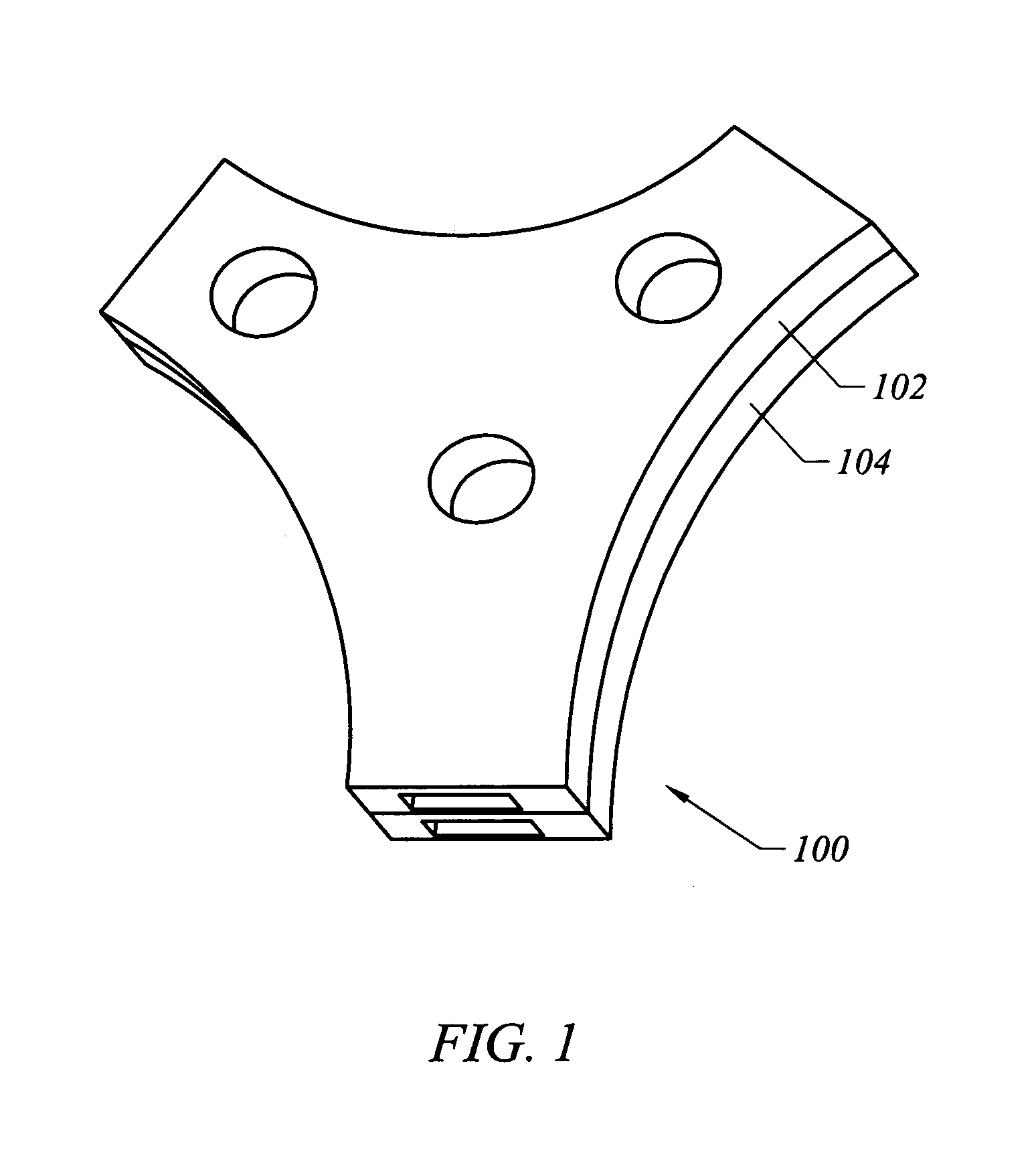
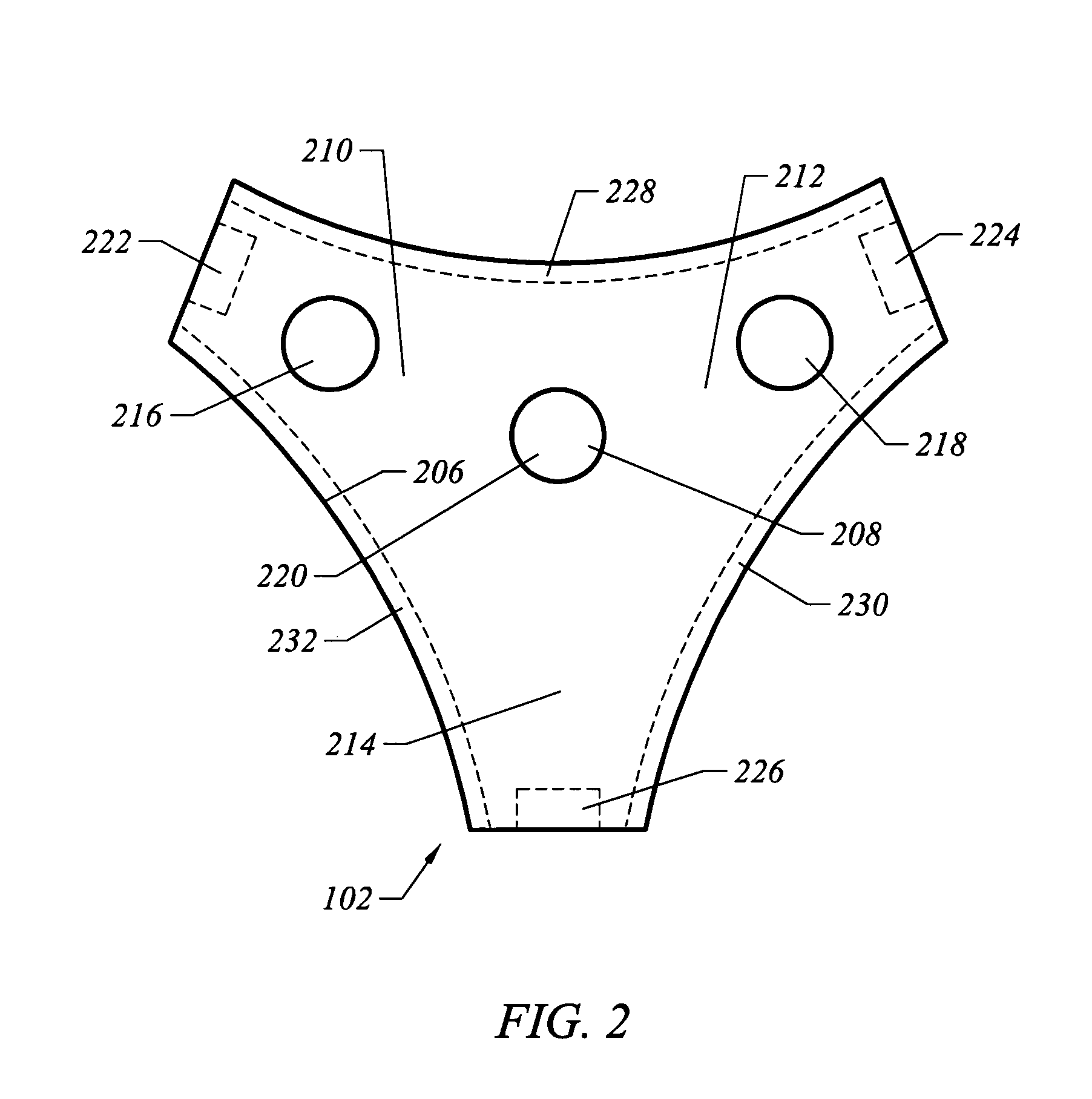
[0037]Typically a power line, such as an overhead power line or a service drop line, is directly connected at one end to a piece of electrical equipment or a structure, such as a utility pole or transformer and at a second end another structure, such as the roof of a house or building. Upon receipt of a tensional force on the power line, such as from a falling tree or branch, the tension on the power line may cause the power line to pull on the equipment or structure at either end resulting in damage to such equipment or structure, a loss of power service and a need for potentially costly repairs.

[0038]Generally, the present invention provides an apparatus and method for electrically connecting a power line to a piece of equipment or to a structure and allows the power line to disconnect from that equipment or structure upon receiving a given amount of tensional force before such tension causes damage to the equipment or structure. More specifically, in one embodiment, the present i...


PUM

PropertyMeasurementUnit
angleaaaaaaaaaa
angleaaaaaaaaaa
tensional forceaaaaaaaaaa

Abstract

An apparatus for connecting two pairs of conductors and one pair of ground wires and for allowing separation of the same upon the application of a tensional force upon at least one of the conductors or ground wires. The apparatus includes two plates that each defines three holes configured to receive two conductors and a ground wire, wherein the plates are positioned adjacent to each other such that the respective holes in each plate are aligned such that the conductors and ground wires coming from each plate would be in physical contact. Three connectors hold the plates together. The first two connectors are configured to release the plates upon the application of a tensional force on the conductors or ground wires before the third connector releases the plates, thereby separating the conductors before separating the ground wires.

Description

[0001]This application claims the benefit of U.S. Provisional Application No. 60 / 529,236, filed Dec. 11, 2003, entitled “Apparatus and Method for Electrically and Mechanically Connecting and Disconnecting a Power Line,” which is incorporated by reference herein in their entirety.BACKGROUND OF THE INVENTION[0002]1. Field of the Invention[0003]The present invention relates generally to electric power lines. More specifically, the invention relates to an apparatus and method for mechanically and electrically disconnecting a service drop power line.[0004]2. Description of Related Art[0005]Power outages not only inconvenience utility customers but may severely damage the utility company's service hardware and any structure attached to the utility lines, as well as creating a hazard with the possibility of dropping a live electrical wire. When such damage occurs, it is often costly for the utility company to repair and replace parts but also costly when such damage causes long delays in r...

Claims


Application Information

Patent Timeline
Patent Type & Authority Patents(United States)
IPC IPC(8): H01R13/633H01R13/639H02G7/04H02G7/18
CPCH01R13/633H01R13/639H02G7/04H02G7/18Y10T29/49195Y10S439/923Y10T29/49174Y10T29/49185
Inventor OSTENDORP, MARKUS
Owner ELECTRIC POWER RES INST INC
Why Eureka
Try Eureka