Apparatus for handling electronic components and method for controlling temperature of electronic components

a technology for electronic components and apparatuses, applied in the direction of measurement devices, semiconductor/solid-state device testing/measurement, instruments, etc., can solve the problems of inability to accurately test ic devices, poor product quality, and sometimes excessive rise of ic devices during testing, etc., to achieve high radiation capacity of heat absorption and radiating bodies

Inactive Publication Date: 2005-12-06
ADVANTEST CORP
View PDF6 Cites 23 Cited by
  • Summary
  • Abstract
  • Description
  • Claims
  • Application Information

AI Technical Summary

Benefits of technology

[0013]Furthermore, when the temperature of the electronic components to be tested rises due to heat generation by the components themselves, the heat of the electronic components to be tested is transmitted from the pushers to the heat absorbing and radiating bodies and then radiated from the heat absorbing and radiating bodies. In accordance with the above-described inventions (1, 2, 11), because the heat absorbing and radiating bodies can be temperature controlled, cooling the heat absorbing and radiating bodies to the prescribed temperature makes it possible to prevent excess increase in temperature of the electronic components to be tested. At this time, because the contact portions of the head test can be temperature controlled separately, cooling thereof following cooling of the heat absorbing and radiating bodies can be prevented and excess temperature decrease in the contact portions and, therefore, in the electronic components to be tested can be prevented.
[0028]According to the above-described invention (10), the pushers relating to the heat absorbing and radiating bodies to which the temperature-adjusting medium is supplied at the beginning can be cooled despite a low heat absorption and radiation capacity of the heat absorbing and radiating bodies, because the temperature of the temperature-adjusting medium is low. The pushers relating to the heat absorbing and radiating bodies to which the temperature-adjusting medium is supplied at the end can be cooled despite the increase in the temperature of the temperature-adjusting medium, because the heat absorption and radiation capacity of the heat absorbing and radiating bodies is high. With the invention (10), each pusher can be thus controlled to an almost constant temperature.

Problems solved by technology

Furthermore, when the IC devices are tested which generated heat by themselves during operation (during testing), the temperature of IC devices sometimes excessively rises above the set temperature during testing.
If the temperature of IC devices thus shifts significantly from the set temperature, accurate testing of the IC devices cannot be conducted.
For example, when testing of IC devices is conducted at a temperature excessively lower than the set temperature, defective products are considered to be good products, and when testing of IC devices is conducted at a temperature excessively higher than the set temperature, good products are considered to be defective products and yield is reduced.
However, because the test chamber (sockets) has to be maintained at the prescribed temperature, a limitation is placed on the decrease in air temperature.

Method used


Image

  • Apparatus for handling electronic components and method for controlling temperature of electronic components
  • Apparatus for handling electronic components and method for controlling temperature of electronic components
  • Apparatus for handling electronic components and method for controlling temperature of electronic components

Examples


first embodiment

[First Embodiment]

[0043]The first embodiment of the present invention will be described below with reference to the appended drawings.

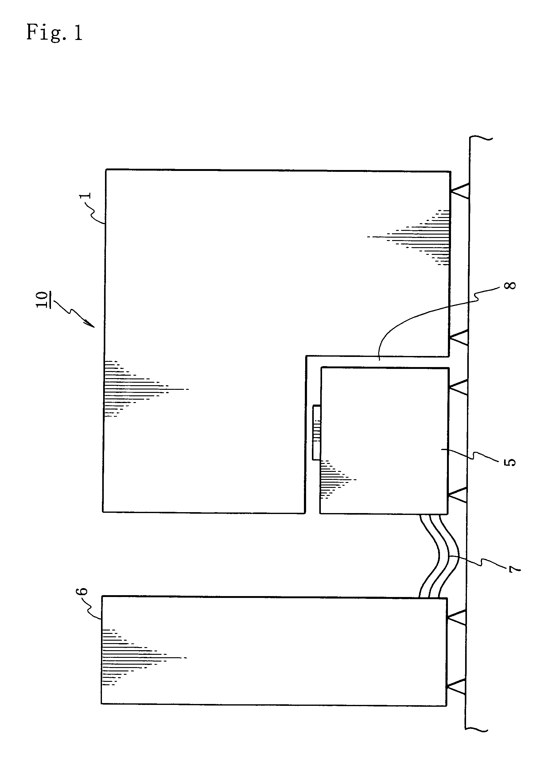
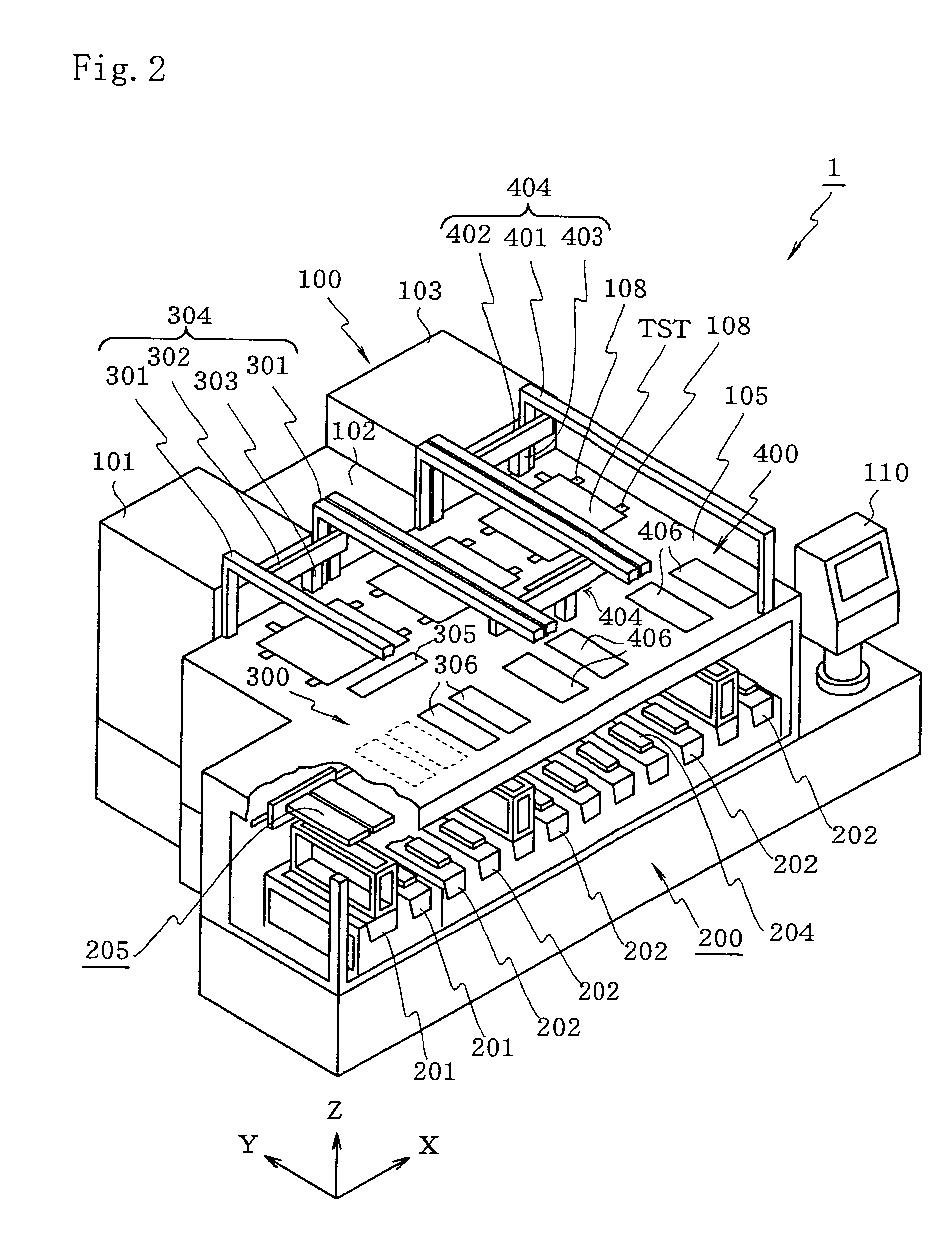
[0044]First, the entire structure of an IC device test apparatus equipped with a handler of the present embodiment will be explained. As shown in FIG. 1, an IC device test apparatus 10 comprises a handler 1, a test head 5, and a main testing unit 6. The handler 1 executes an action of successively transporting IC devices (an example of electronic components) which are to be tested into sockets provided on the test head 5, classifying the tested IC devices according to the test results and storing them in the prescribed tray.

[0045]The sockets (equivalent to contact portions in accordance with the present invention) provided on the test head 5 are electrically connected via a cable 7 to the main testing unit 6, and are used for connecting the IC devices removably installed in the sockets to the main testing unit 6 via the cable 7 and for testing the IC ...

second embodiment

[Second Embodiment]

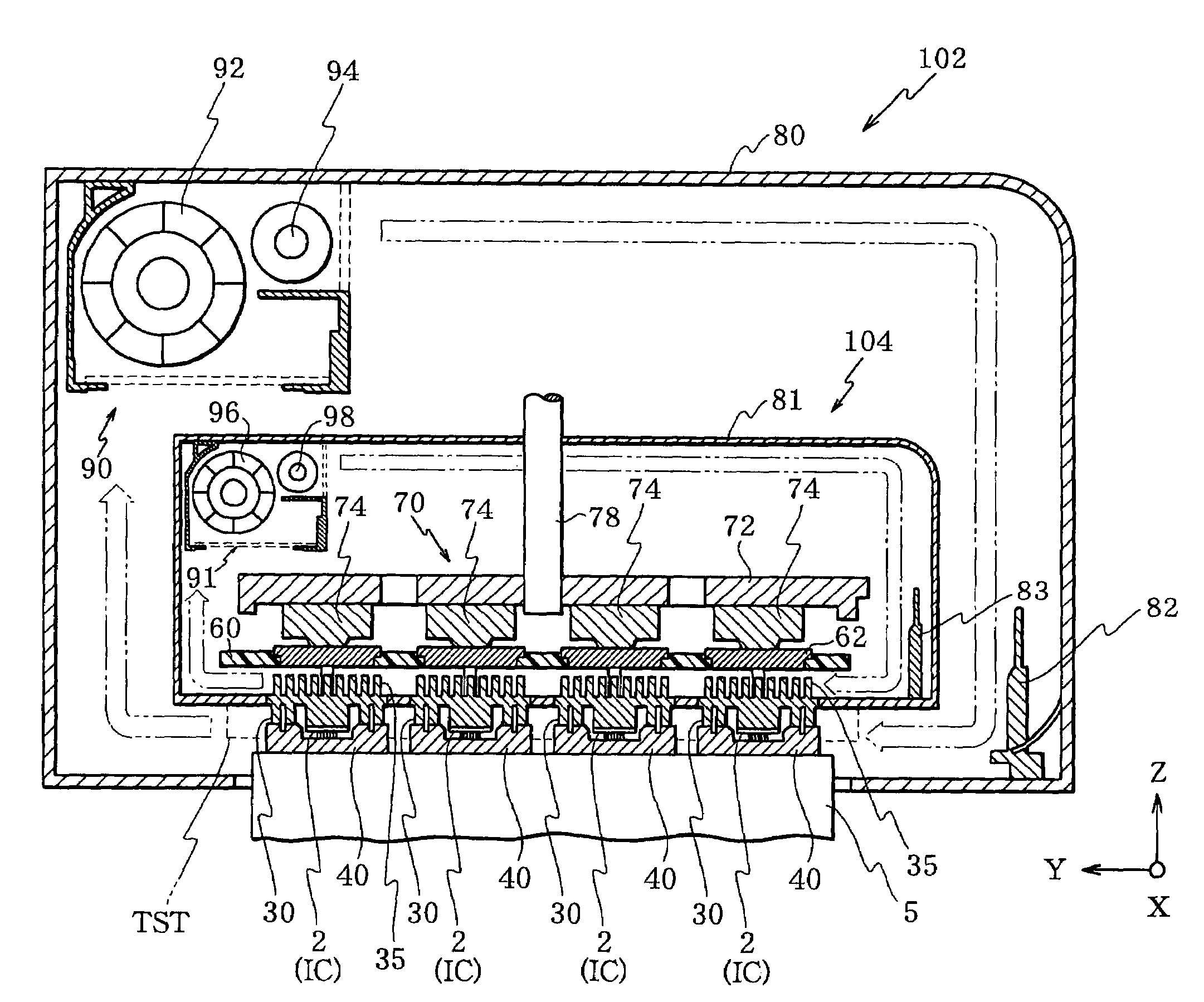
[0097]The second embodiment of the present invention will be described below. The handler of the second embodiment has a structure almost identical to that of the handler 1 of the first embodiment. However, as shown in FIG. 10, it differs from the handler 1 of the first embodiment in that through holes 721 are formed in the drive plate 72 contained inside the chamber 104 for heat sink, through holes 601 are formed in the match plate 60, and pipe members 76 are provided for linking the through holes 721 of drive plate 72 with the through holes 601 of match plate 60.

[0098]Warm or cold blast (air) generated via the heat exchanger 98 of air blowing unit for temperature adjustment 91 inside the inner chamber 104 of such a handler circulates inside the casing by flowing along the Y axis direction above the casing 81, coming down via through holes 721 of drive plate 72, pipe members 76, and through holes 601 of match plate 60 (partly along the side wall of the casing on ...

third embodiment

[Third Embodiment]

[0101]The third embodiment of the present invention will be described below. The handler of the third embodiment has a structure similar to that of the handler of the second embodiment, but it comprises no casing 81 (inner chamber 104) containing inside thereof the drive shaft 78, drive plate 72, pressing member 74, match plate 60, and adaptor 62. Instead, as shown in FIG. 11, the handler comprises heat sink chambers 106 in which only the heat sinks 35 of a plurality of pushers 30 belonging to the same row are sealed with ducts 84.

[0102]A temperature adjusting medium such as warm blast or cool air from an air blowing unit for temperature adjustment (not shown in the figure), or warm water or cool water from a water pump for temperature adjustment flows inside the ducts 84 constituting the heat sink chambers 106, and the temperature control of heat sinks 35 in each row is conducted by this temperature adjusting medium.

[0103]Warm or cold blast (air) generated via the...


PUM


Abstract

A handler 1 is provided with an inner chamber 104 containing inside thereof heat sinks 40 of pushers 30, a temperature adjusting unit 91 for controlling the atmosphere temperature inside the inner chamber 104, a test chamber 102 containing inside thereof sockets 40 located on the test head 5 and the inner chamber 104, and a temperature adjusting unit 90 for controlling the atmosphere temperature inside the test chamber 102. With such a handler 1, the temperature control can be conducted so that the temperature of electronic components is brought close to the set temperature of the target test.

Description

[0001]This application is a Continuation of PCT / JP02 / 06851 filed Jul. 5, 2002.TECHNICAL FIELD[0002]The present invention relates to an apparatus for handling electronic components that is capable of handling electronic components which are to be tested, for testing the electronic components such as IC devices, and more particularly to an apparatus for handling electronic components that is capable of controlling the temperature of electronic components which are to be tested and to a method for controlling the temperature of electronic components which are to be tested.BACKGROUND ART[0003]Test apparatuses for testing electronic components that have been finally fabricated are necessary in the fabrication of electronic components such as IC devices or the like. Apparatuses for testing a plurality of IC devices at one time under temperature conditions (thermal stress conditions) higher than normal temperature are known as a kind of such test apparatuses.[0004]In such test apparatuses,...

Claims


Application Information

Patent Timeline
Patent Type & Authority Patents(United States)
IPC IPC(8): G01R31/28G01R31/26H01L21/66
CPCG01R31/2862G01R31/2868G01R31/2874G01R31/2867G01R31/26H01L22/00
Inventor YAMASHITA, TSUYOSHIIGARASHI, NORIYUKI
Owner ADVANTEST CORP
Why Eureka
Try Eureka