Radio frequency transceiver

a radio frequency transceiver and radio frequency technology, applied in the field of radio frequency transceivers, can solve the problems of difficult calibration of oscillators and dielectric reference oscillators, affecting the accuracy and reliability of transceivers, and often exhibiting poor reliability

Inactive Publication Date: 2005-12-06
YAZAKI NORTH AMERICA
View PDF9 Cites 15 Cited by
  • Summary
  • Abstract
  • Description
  • Claims
  • Application Information

AI Technical Summary

Problems solved by technology

However, in many instances, transceivers must endure harsh physical conditions, such as shocks, vibrations, and varying environmental conditions, including temperatures ranging from −40° to 100° C. These harsh physical conditions may affect the accuracy and reliability of the transceiver.
First, the waveform signal generated by a dielectric reference oscillator can be significantly non-linear.
As a result, the waveform signal generated by the dielectric reference oscillator is not an accurate representation of the original reference signal that is inputted into the dielectric oscillator: Second, Gunn oscillators and dielectric reference oscillators are notoriously hard to calibrate and often exhibit poor reliability when subject to non-static environmental conditions, such as temperature variances.
Third, Gunn oscillators and dielectric reference oscillators are relatively expensive, particularly when they are designed to operate at relatively high frequencies, such as is required in automotive radar systems (i.e., 76–77 GHz).
Finally, Gunn oscillators and dielectric reference oscillators suffer from significant phase noise, thereby diminishing their detection capabilities.

Method used


Image

  • Radio frequency transceiver
  • Radio frequency transceiver
  • Radio frequency transceiver

Examples


Embodiment Construction

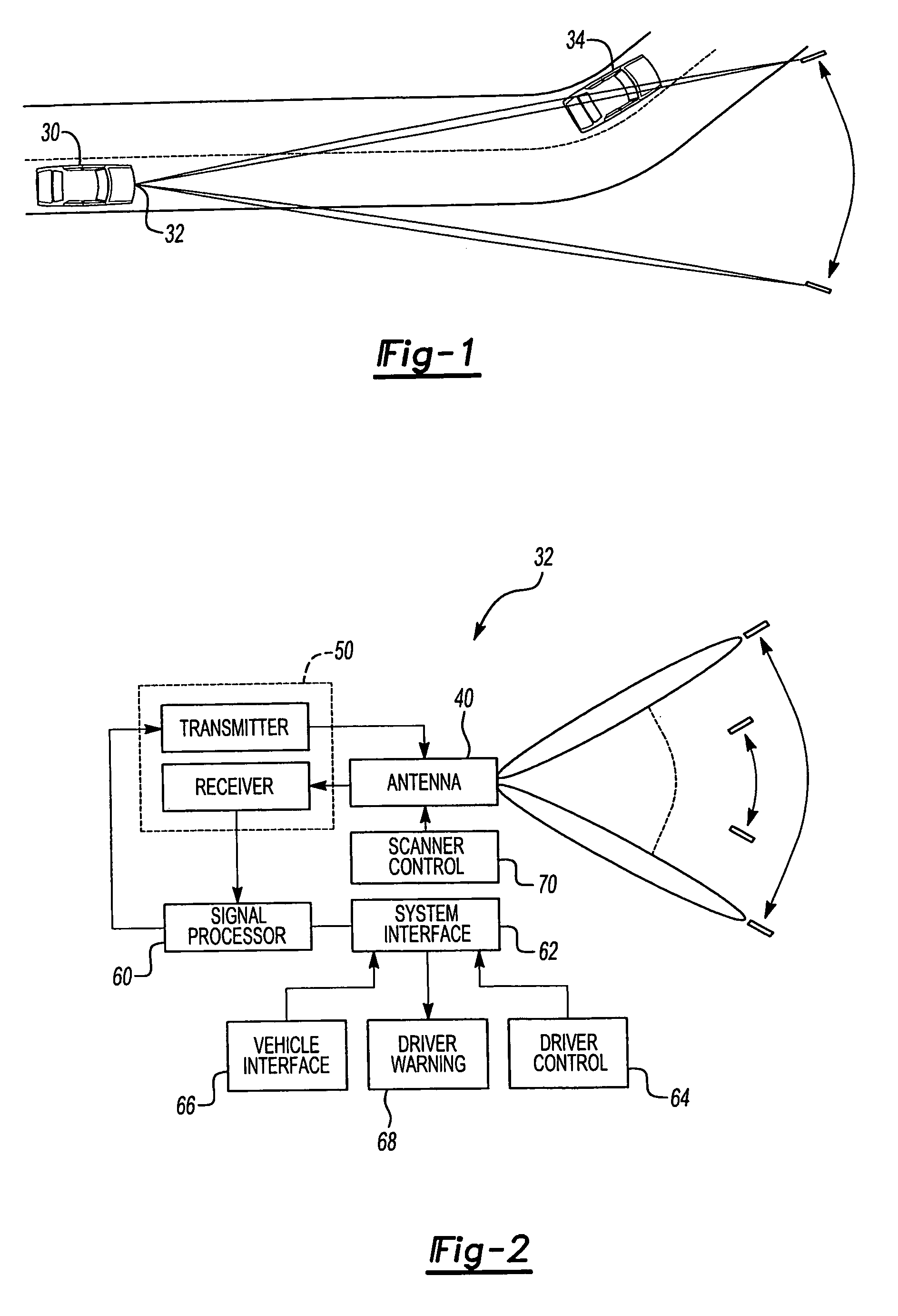
[0013]FIG. 1 illustrates one environment in which the present invention could be beneficially utilized. A traveling vehicle 30 has a vehicular collision warning system 32 mounted at a front portion of the vehicle body. The collision warning system emits a forward signal, such as a radar wave, from the vehicle and also receives a reflected wave from an obstacle, such as another vehicle 34, which is driving towards or away from vehicle 32. The collision warning system measures the distance between the traveling vehicle 30 and the other vehicle 34. If the system detects an object directly in front of the traveling vehicle, it automatically activates an alarm or adaptively controls the vehicle by, for example, activating a brake to supply a braking force to the vehicle's wheels. Thus, the vehicular collision warning system notifies the driver of an impending collision and / or initiates evasive action to avoid a collision or actively adjusts the vehicle speed to maintain a time headway to...


PUM


Abstract

A transceiver that includes a radio frequency source comprised of a monolithic millimeter wave integrated circuit. The transceiver generates a signal of a first frequency, which is then converted to a signal of a second frequency as the signal is conveyed through the transceiver. The value of the second frequency exceeds that of the first frequency.

Description

TECHNICAL FIELD OF THE INVENTION[0001]The present invention relates generally to a transceiver, and, more specifically, a transceiver that uses monolithic millimeter wave integrated circuitry (“MMIC”).BACKGROUND OF THE INVENTION[0002]Radar systems are used in a variety of applications. One fast-emerging application for radar systems is in connection with automotive collision warning systems that warn a driver of impending collisions between the driver's vehicle and other objects using a visual or audible signal. Some collision warning systems further include the ability to assist the driver to avoid the impending collision by automatically adjusting the vehicle's speed or direction without intervention from the driver. Yet another emerging application for radar systems includes adaptive cruise control applications wherein a vehicle's cruise control speed can be automatically adjusted in response to the detection of one or more other proximate vehicles on the road. In addition to the...

Claims


Application Information

Patent Timeline
Patent Type & Authority Patents(United States)
IPC IPC(8): G01S13/00
CPCG01S7/35G01S7/4008G01S2013/9346G01S2013/935G01S2013/93185G01S2013/9319
Inventor DEEM, JAKEWILSON, TERRY B.
Owner YAZAKI NORTH AMERICA
Why Eureka
Try Eureka