Thermal head

a head and thermal technology, applied in the field of thermal head, can solve problems such as deteriorating printing quality, and achieve the effect of reducing creases of ink films and excellent printing quality

Inactive Publication Date: 2005-12-06
ALPS ALPINE CO LTD
View PDF7 Cites 5 Cited by
  • Summary
  • Abstract
  • Description
  • Claims
  • Application Information

AI Technical Summary

Benefits of technology

[0019]The present invention has been made in view of the above-mentioned problems, and it is an object of the present invention to provide a thermal head reducing creases of an ink film and resultantly offering excellent printing quality when used in a thermal-transfer printer.

Problems solved by technology

Furthermore, although the thermal head 101 comes into contact with the ink film 111 and irons out its creases upstream of the abutment position when the thermal head 101 has a small abutment angle, when the thermal head 101 has a large abutment angle, a contact area formed between the thermal head 101 and the ink film 111 becomes smaller upstream of the abutment position, whereby creases of the ink film 111 become more strongly influential to printing quality, thus resulting in deteriorated printing quality.

Method used


Image

  • Thermal head
  • Thermal head
  • Thermal head

Examples


Embodiment Construction

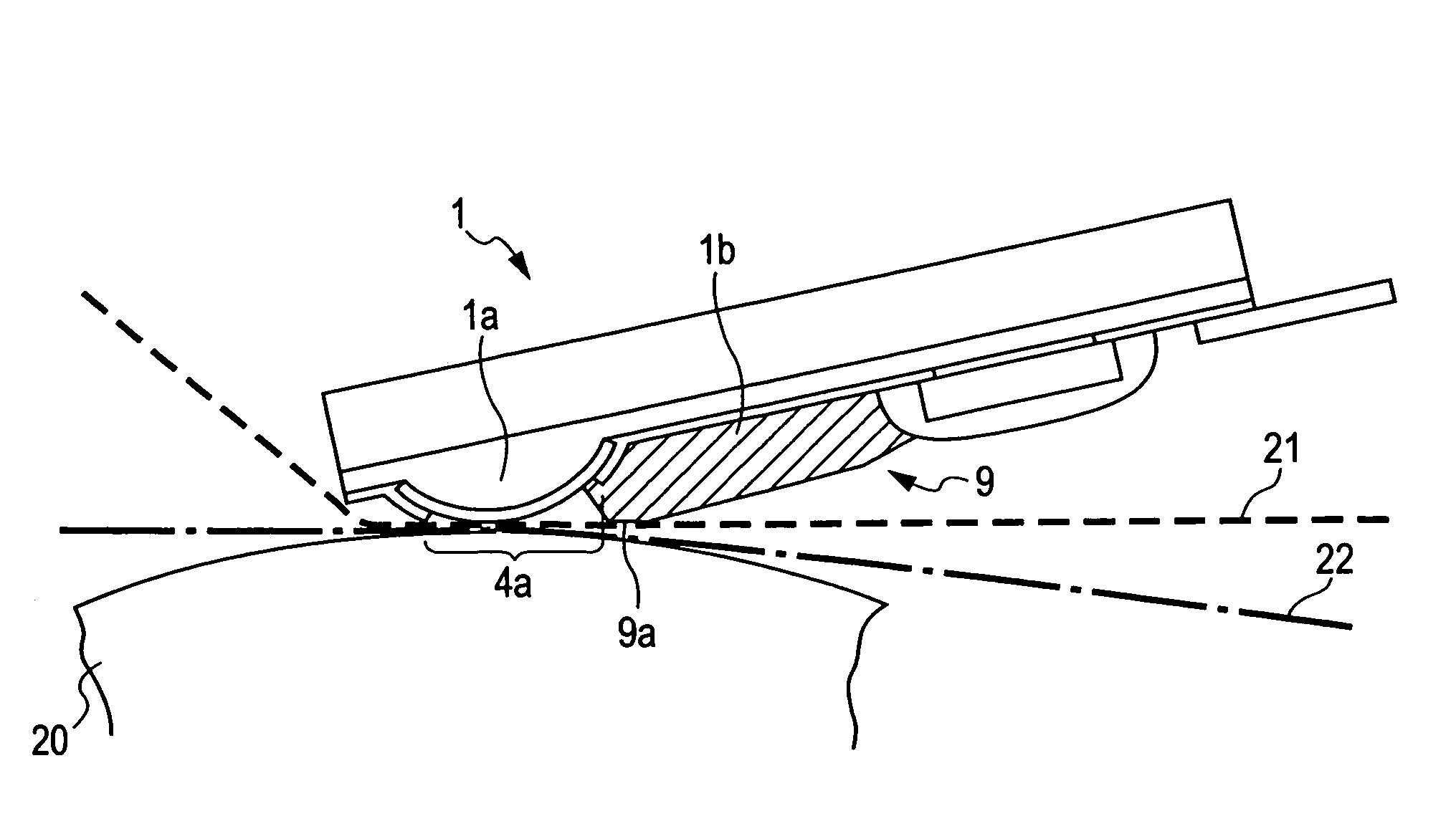
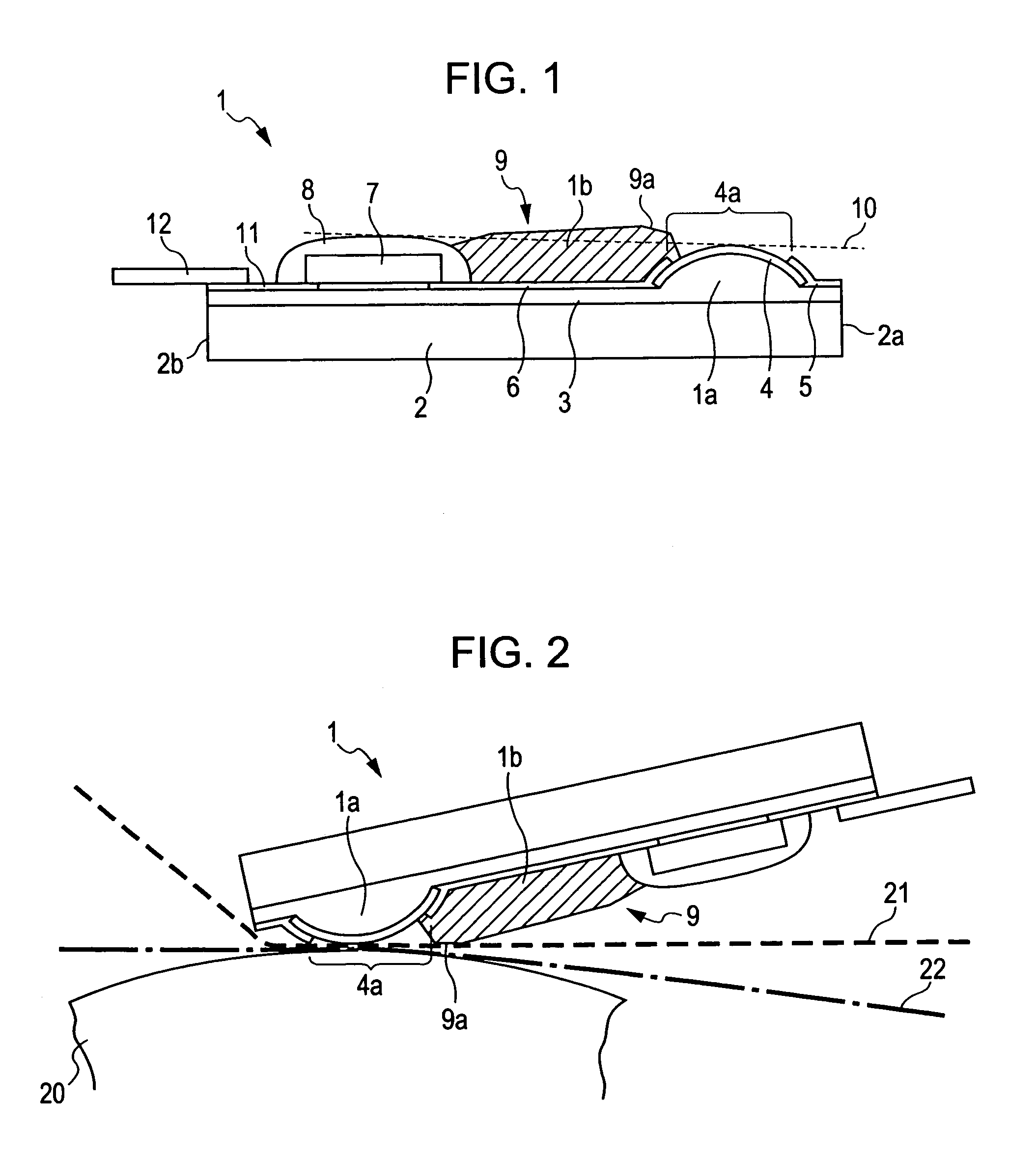
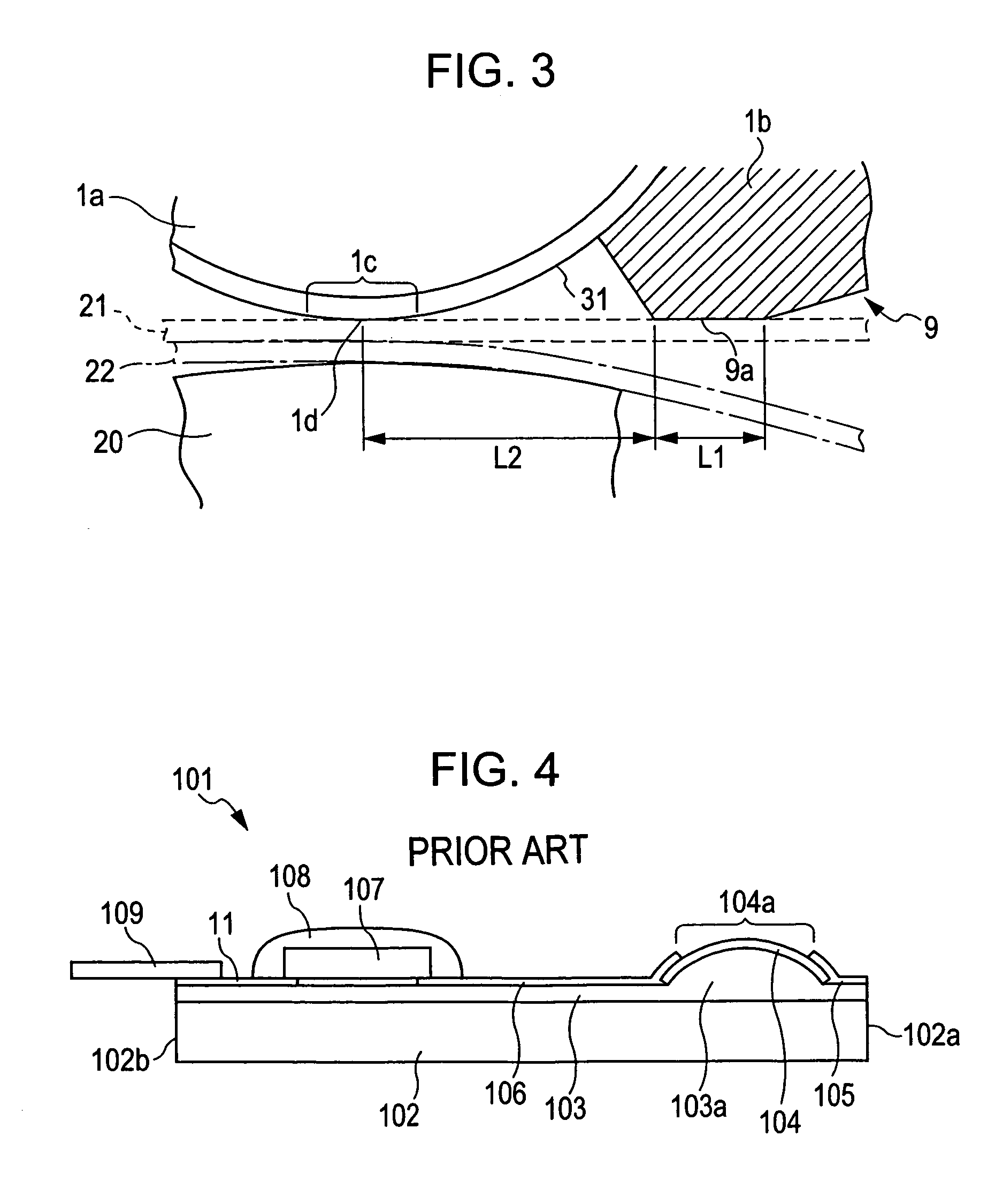
[0030]An embodiment of the present invention will be described with reference to FIGS. 1 to 3. FIG. 1 is a schematic sectional view of the overall structure of a thermal head 1 according the present invention, FIG. 2 is a schematic sectional view of the thermal head 1, illustrating its printing operation, and FIG. 3 is a magnified view of an essential part of the thermal head 1.

[0031]As shown in FIGS. 1 and 2, the thermal head 1 according the present invention has a structure in which a plurality of heating elements 4a are linearly formed on respective first projections 1a serving as a part of a heat-insulating layer 3 and, with respect to each heating element 1a, includes a driver IC 7 connected to a common electrode 5 and an individual electrode 6 extending from the heating element 4a; a sealing member 8 sealing the driver IC 7, and a second projection 1b lying upstream, with respect to the transport route of an ink film 21, of an abutment position 1d (see FIG. 3) serving as the c...


PUM


Abstract

In order to reduce creases of an ink film so as to offer excellent printing quality, a thermal head for use in a thermal-transfer printer includes a heat-insulating layer; a first projection serving as a part of the heat-insulating layer; a heating element formed on the first projection; common and individual electrodes connected to the heating element; a driver IC connected to these two electrodes; a sealing member sealing the driver IC; and a second projection protruding upstream, with respect to the transport route of the ink film, of the center of a section where the heating element comes into contact with a platen, so as to lie beyond a line connecting the apexes of the first projection and the sealing member.

Description

[0001]This application claims the benefit of priority to Japanese Patent Application No. 2004-017080, filed on Jan. 26, 2004, herein incorporated by reference.BACKGROUND OF THE INVENTION[0002]1. Field of the Invention[0003]The present invention relates to a thermal head for use in a thermal-transfer printer in which printing is performed by transferring ink of an ink film onto a paper sheet.[0004]2. Description of the Related Art[0005]Hitherto, a known thermal-transfer printer has a structure in which printing is performed by heating heating elements of a thermal head so as to transfer ink applied on the upper surface of an ink film such as an ink ribbon or an ink sheet onto a sheet of paper (hereinafter, simply referred to as a paper sheet. The thermal-transfer printer having such a structure is in heavy use as an output device of a computer, a facsimile machine, a word-processor, a digital still camera, and the like, thanks to its high recording quality, low-noise, low cost, easy ...

Claims


Application Information

Patent Timeline
Patent Type & Authority Patents(United States)
IPC IPC(8): B41J2/32B41J2/335B41J2/345B41J17/30
CPCB41J2/335
Inventor TERAO, HIROTOSHIWAUKE, TOMOKOHOSHINO, HISASHISASAKI, TSUNEYUKI
Owner ALPS ALPINE CO LTD
Why Eureka
Try Eureka