Image pickup system and vehicle-mounted-type sensor system

a pickup system and image technology, applied in the field of image pickup systems, can solve the problems of insufficient knowledge, inconvenient exchange of such sensors, and inability to guarantee image quality, and achieve the effect of ensuring consistent image quality

Inactive Publication Date: 2005-12-06
PANASONIC CORP
View PDF15 Cites 31 Cited by
  • Summary
  • Abstract
  • Description
  • Claims
  • Application Information

AI Technical Summary

Benefits of technology

[0018]Therefore, a first object of the present invention is to provide an image pickup system for concurrently picking up several images, and merging those into one image with an assured consistent image quality on a display.

Problems solved by technology

The issue here is, the image pickup devices each differently adjust amplification ratio and filtering coefficient.
Accordingly, if the resultant image data from each of the image pickup devices are merged together, an image after merging generally lacks consistency of image quality.
The problem is, however, the sensor equipped in the system is a dedicated type specifically for the system.
Therefore, exchange of such sensor is not that simple, for example, with other manufacturer's sensor or any higher-performance sensor.
After exchange, the driver is bothered by the sensor's setting change, resolution and sensitivity adjustment, and positioning, and that may need extensive knowledge.

Method used


Image

  • Image pickup system and vehicle-mounted-type sensor system
  • Image pickup system and vehicle-mounted-type sensor system
  • Image pickup system and vehicle-mounted-type sensor system

Examples


first embodiment

(First Embodiment)

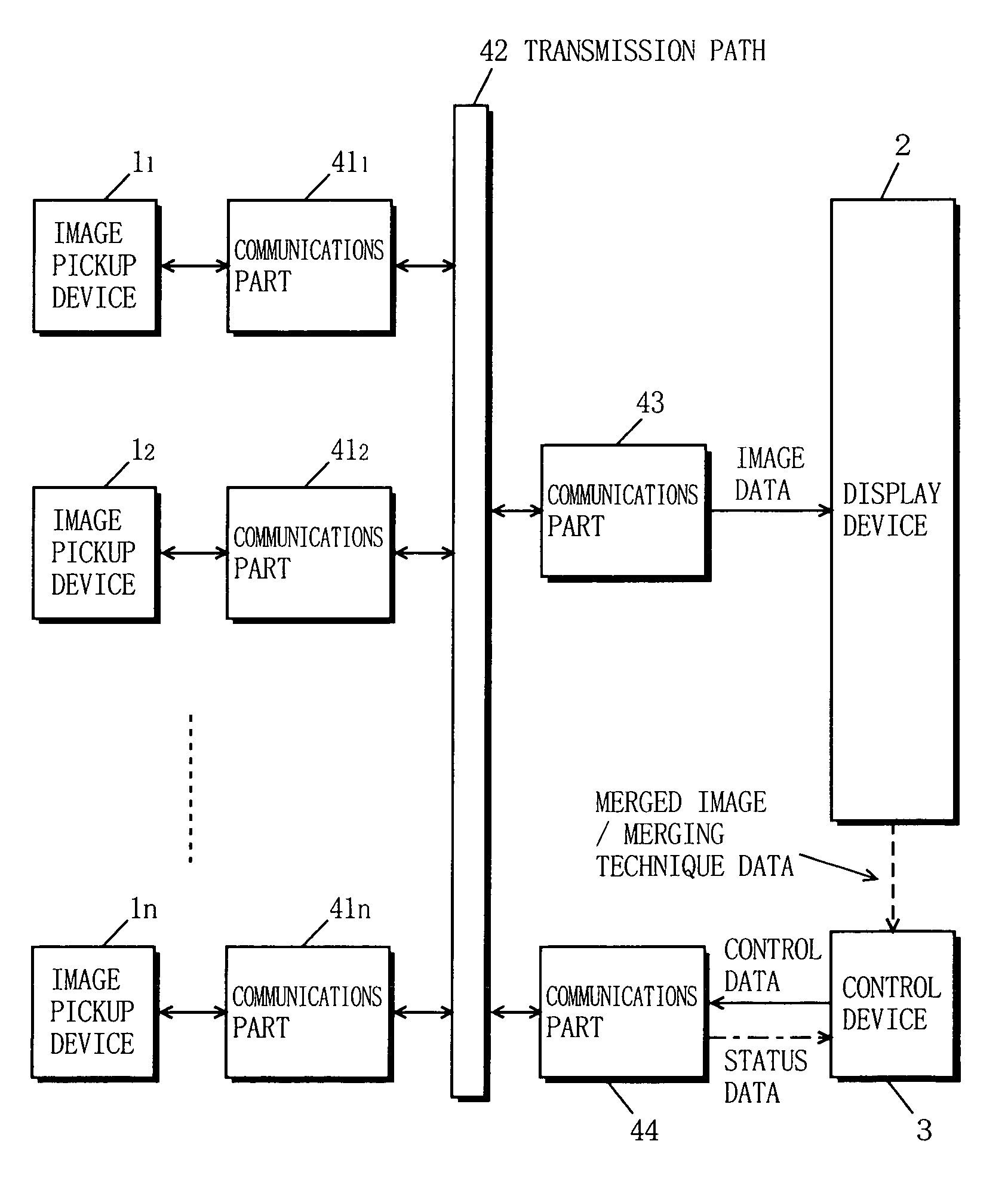
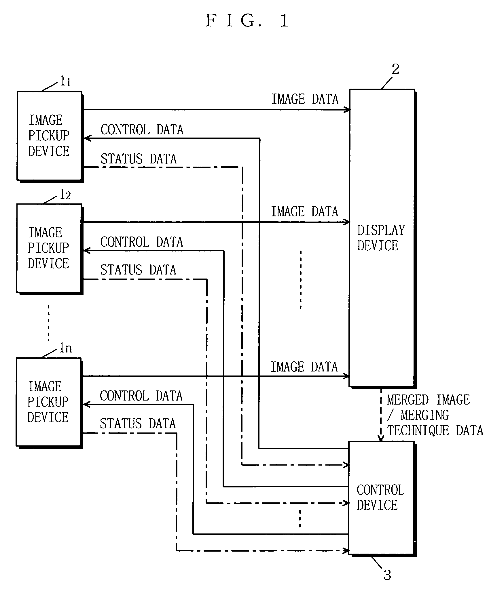
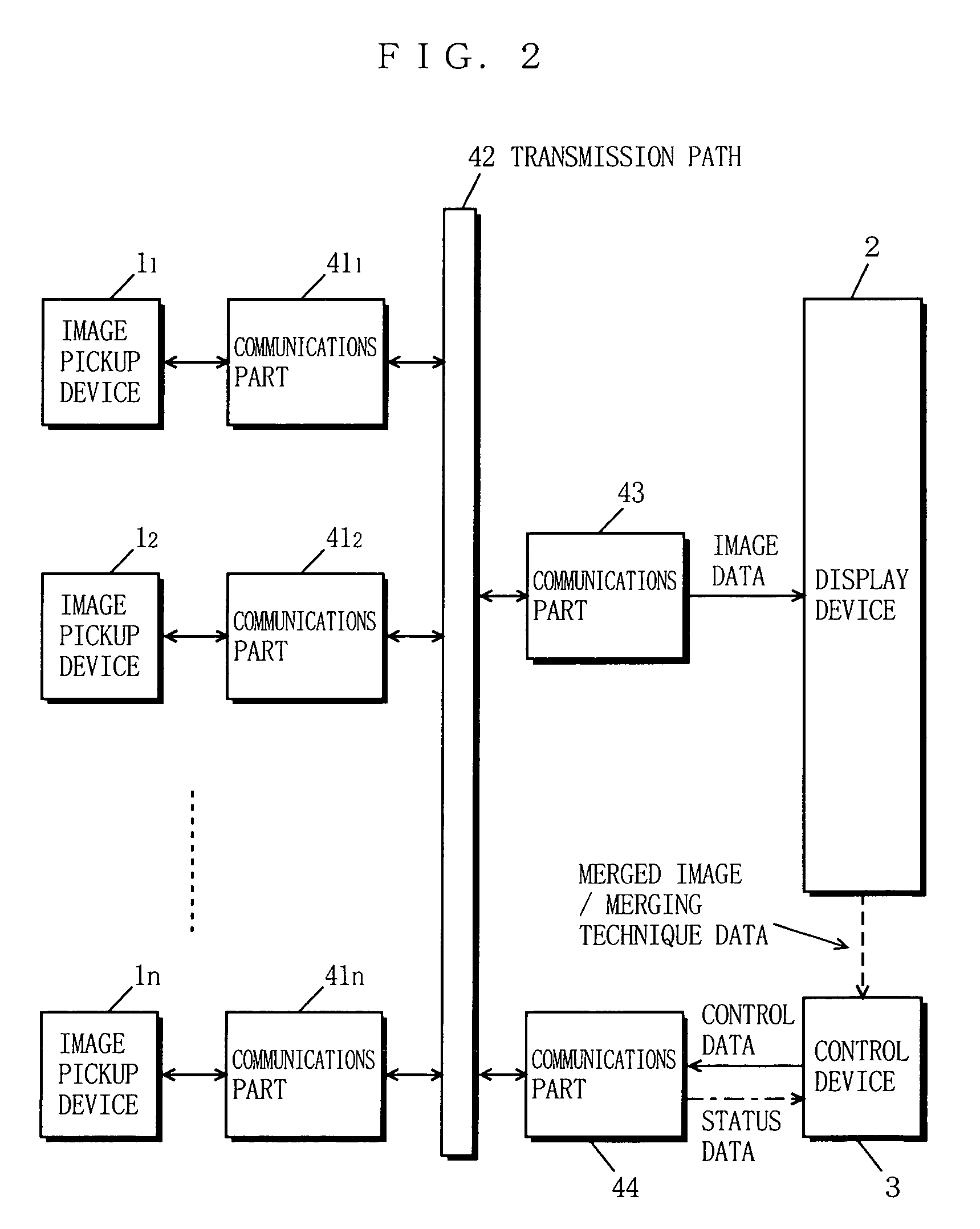
[0272]FIG. 1 is a block diagram showing the structure of an image pickup system according to a first embodiment of the present invention. In FIG. 1, the image pickup system includes a plurality of image pickup devices 1 (denoted by 11 to 1n, where n is an arbitrary integer of two or more), a display device 2, and a control device 3. The image pickup devices 1 are each connected to the display device 2 via a transmission line for image data, and to the control device 3 via both a transmission line for control data and that for status data.

[0273]The control device 3 is connected to the display device 2 via a transmission line for merged image / merging technique data.

[0274]Note herein that, such connection is not always necessary, and it will do as long as the image pickup devices 1 are each connected to the display device 2 via the transmission line for image data, and to the control device 3 via the transmission line for control data (details are left for later descr...

second embodiment

(Second Embodiment)

[0330]In a second embodiment, described is an image pickup system which applies the first control technique described in the first embodiment. In the first control technique, the control device 3 controls the image pickup devices 1 for shared use of a common image quality parameter, which is previously stored in the control device 3.

[0331]The image pickup system of the second embodiment is similar to that of FIG. 1 (or FIG. 2). Further, the image pickup device 1, the display device 2, and the control device 3 of FIG. 1 (or FIG. 2) are similar to those of FIGS. 3 to 6B.

[0332]The second embodiment is provided for describing the operation of the control device 3 to a further degree, and other components already appeared in the first embodiment are considered operationally the same, and not described unless otherwise specified.

[0333]FIG. 3 shows the structure of the control device 3. In FIG. 3, the CPU 301 operates according to the program 304 stored in the ROM 303 wh...

third embodiment

(Third Embodiment)

[0345]In a third embodiment, described is an image pickup system which applies the second control technique described in the first embodiment. In the second control technique, a common image quality parameter is determined by the control device 3 based on the already-set image quality parameters transmitted from the respective image pickup devices 1. Thus determined common image quality parameter is set in the image pickup devices 1 for shared use thereamong.

[0346]The image pickup system of the third embodiment is similar to that of FIG. 1 (or FIG. 2). Further, the image pickup device 1, the display device 2, and the control device 3 of FIG. 1 (or FIG. 2) are similar to those of FIGS. 3 to 6B.

[0347]The third embodiment is provided for describing the operation of the control device 3 to a still further degree, and other components already appeared in the first embodiment are considered operationally the same, and not described unless otherwise specified.

[0348]FIG. 8...


PUM


Abstract

A control device determines whether an image generated by merging several concurrently picked-up images has consistent image quality on a display device. If determined No, image quality parameters set in each image pickup device are so controlled as to make the image quality of the merged image consistent. Therefore, the merged image can assuredly have consistent image quality. Further, a signal processing device detects, based on positions of nodes and attributes of cameras, a connection indicating which node is connected to which camera and with what attribute. The signal processing device in advance stores every detectable connection and a plurality of image processing programs corresponding to each connection, and selects and carries out one of the image processing programs corresponding to the detected connection.

Description

BACKGROUND OF THE INVENTION[0001]1. Field of the Invention[0002]The present invention relates to image pickup systems and, more specifically, to an image pickup system for concurrently picking up several images and merging those into one for display. The present invention also relates to sensor systems and, more specifically, to a vehicle-mounted-type sensor system for sensing and advising a driver of a vehicle, as a safeguard, in what environmental state a specific range around the vehicle is.[0003]2. Description of the Background Art[0004](First Background Art)[0005]FIG. 38 shows an exemplary structure of a conventional image pickup device. In FIG. 38, the conventional image pickup device includes an image pickup part 91, a signal processing part 92, and ROM 93.[0006]The image pickup part 91 includes a CCD, for example, and an optically picked up image is converted into an electrical signal therein f or output as image pickup data. The image pickup data is then forwarded to the si...

Claims


Application Information

Patent Timeline
Patent Type & Authority Patents(United States)
IPC IPC(8): H04N5/232H04N7/18
CPCH04N5/232H04N5/23206H04N5/23238H04N7/181H04N23/698
Inventor KATTA, NOBORUKAWATA, HIROTSUGUIBARAKI, SUSUMUSAKAI, TAKAHISAMORI, TOSHIAKIYAMAMOTO, AKIHIROKUROSAKI, TOSHIHIKOMIZUGUCHI, YUJI
Owner PANASONIC CORP
Why Eureka
Try Eureka