
Liquid crystal display

a technology of liquid crystal display and display screen, which is applied in the field of liquid crystal display, can solve the problems of decreased contrast ratio and gray scale inversion of va lcd, and is less desirable in many applications, such as flat panel television screens and large computer screens, and achieves improved viewing angle performance, wide viewing angle, and high contrast

Inactive Publication Date: 2005-12-06
INNOLUX CORP
View PDF4 Cites 14 Cited by
  • Summary
  • Abstract
  • Description
  • Claims
  • Application Information

AI Technical Summary

Benefits of technology

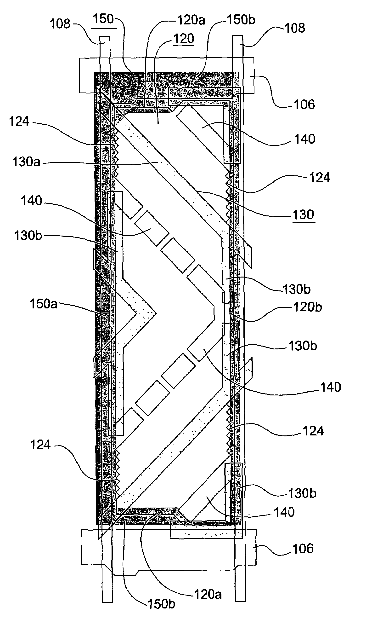
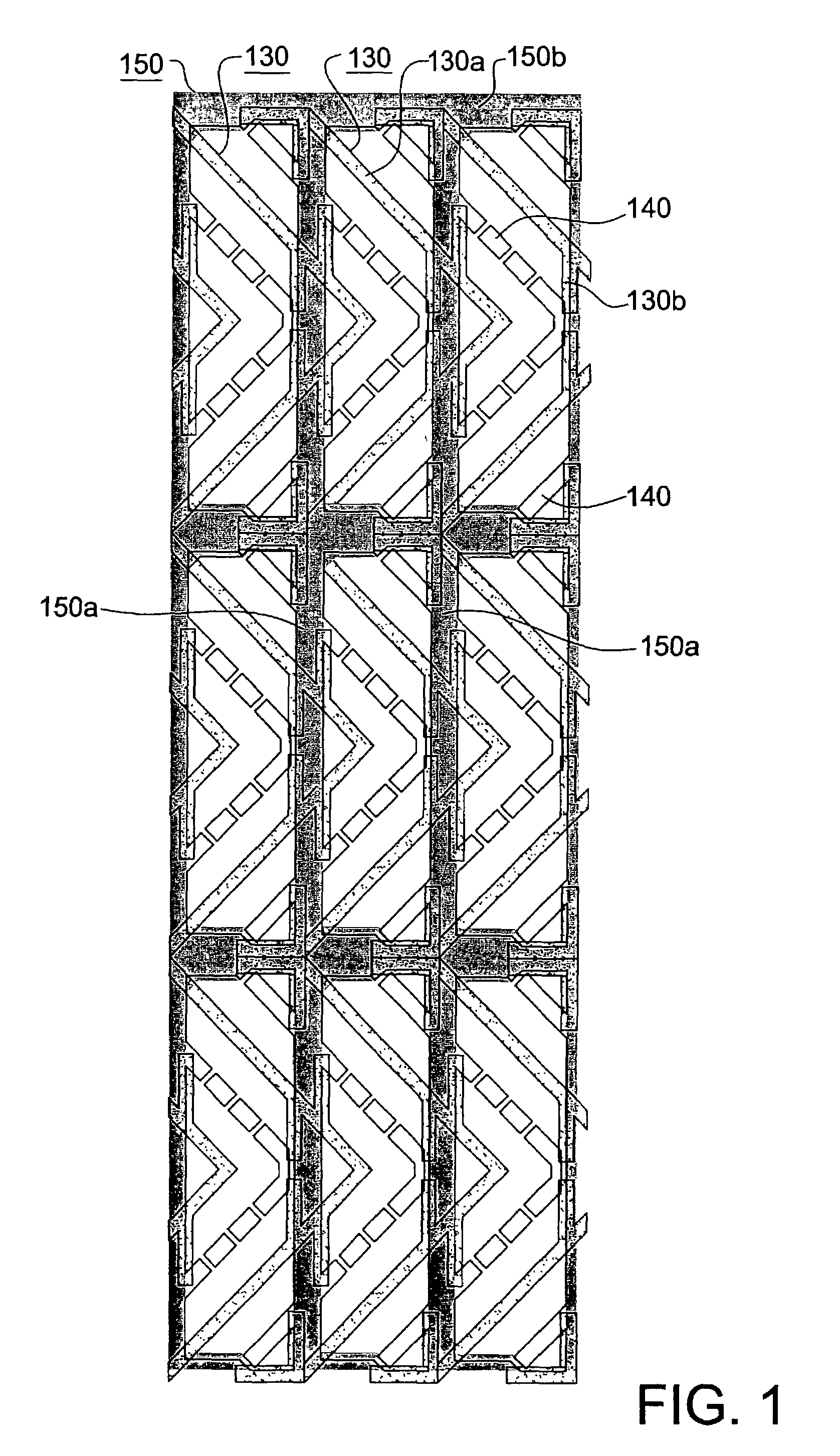
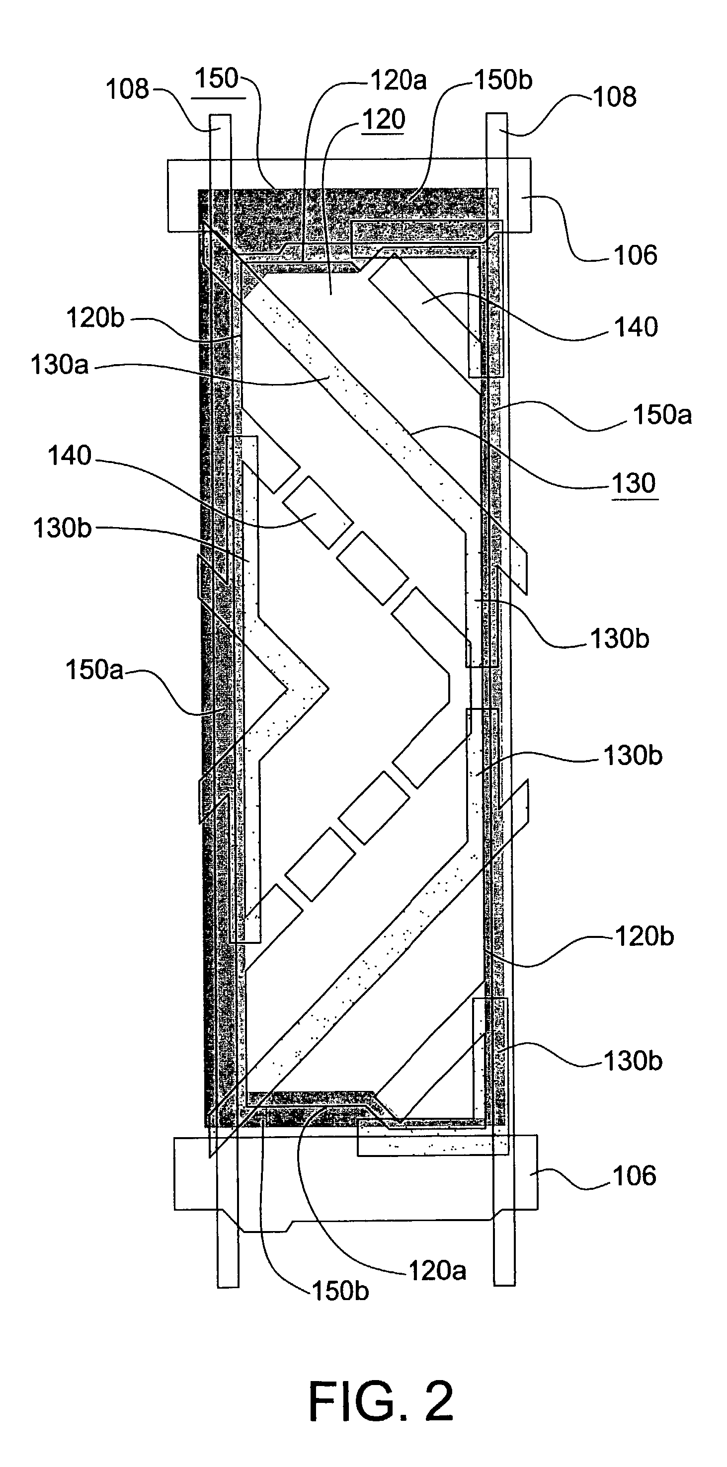
The present invention provides a vertically-aligned LCD with high contrast over a wide viewing angle. The invention includes a light-shielding matrix with columns and rows, and protrusions with branches and slits arranged in a way that reduces disclination and display defects. The second edges of the pixel electrodes have recesses to reduce crosstalk. These technical effects improve the viewing angle performance of the VA LCD.

Problems solved by technology

However, the VA LCDs still suffer from the problems of decreased contrast ratio and gray scale inversion when viewed in a direction not perpendicular to the display area.
The contrast ratio between a light transmissive state (white) and a non-transmissive state (black) decreases drastically at an angle not perpendicular to the display, thereby making it less desirable in many applications, such as flat panel television screens and large computer screens.

Method used


Image

  • Liquid crystal display
  • Liquid crystal display
  • Liquid crystal display

Examples


second embodiment

[0026]FIG. 3 shows the pixel region of a vertically-aligned LCD according to the present invention. This LCD is characterized in that each column 150a of the light-shielding matrix has a plurality of bulged portions (only four bulged portions 150c denoted in FIG. 3) disposed in each pixel region. In this embodiment, areas on the first substrate facing the second edges of the pixel electrodes between the main bodies 130a of the protrusions and the slits 140 are all covered by the bulged portions 150c and the branches 130b of the protrusions, thereby significantly blocking the darkening area caused by crosstalk. It is noted that the branches 130b are not an essential part of the present invention. Alternatively, the bulged portions of each column 150a of the light-shielding matrix may be designed to substitute for the branches 130b.

third embodiment

[0027]FIG. 4 shows the pixel region of a vertically-aligned LCD according to the present invention. The LCD is characterized in that the second edges 120b of the pixel electrodes 120 have a plurality of recesses 122 formed outside the branches 130b of the protrusions so as to relatively increase the minimum distance between the second edge 120b of the pixel electrode and the data line, thereby significantly reducing the problem of crosstalk.

fourth embodiment

[0028]FIG. 5 shows the pixel region of a vertically-aligned LCD according to the present invention. The LCD is characterized by provided with both the bulged portions 150c and the recesses 122, thereby reducing the aforementioned problems.


PUM

PropertyMeasurementUnit
angleaaaaaaaaaa
angleaaaaaaaaaa
dielectric constant anisotropyaaaaaaaaaa

Abstract

A liquid crystal display mainly includes a first substrate and a second substrate processed for vertical alignment; a liquid crystal having a negative dielectric constant anisotropy and being sandwiched between the first and second substrates; an array of protrusions arranged in parallel to one another on the first substrate; and an array of slits provided on the pixel electrodes. The second substrate is provided with a plurality of gate lines, a plurality of data lines and a plurality of pixel electrodes. The pixel electrodes have first edges parallel to the gate lines and second edges parallel to the data lines. The protrusions have branches formed at positions facing the second edges of the pixel electrode in a manner that the angle included between the branches of the protrusions and the slits is kept at most 45 degrees.

Description

BACKGROUND OF THE INVENTION[0001]1. Field of the Invention[0002]The present invention generally relates to a liquid crystal display (LCD), and more particularly to a vertically-aligned (VA) LCD wherein the liquid crystal molecules inside the pixels are oriented to form a plurality of mutually different directions.[0003]2. Description of the Related Art[0004]Liquid crystal display device mainly comprises a liquid crystal display unit having two glass substrates oppositely positioned and a liquid crystal layer interposed therebetween. Vertically-aligned (VA) LCD is a mode using a negative liquid crystal material and vertical alignment films. When no voltage is applied, liquid crystal molecules are aligned in a vertical direction and a black display appears. When a predetermined voltage is applied, the liquid crystal molecules are aligned in a horizontal direction and a white display appears. Compared to the twisted nematic (TN) LCD, the vertically-aligned (VA) LCD provides higher cont...

Claims


Application Information

Patent Timeline
Patent Type & Authority Patents(United States)
IPC IPC(8): G02B5/20G02F1/1333G02F1/1335G02F1/1343G02B5/00G02F1/139
CPCG02F1/1393G02F1/133512G02F1/133707
Inventor LU, RUNG NANWU, YUAN LIANGLIOU, CHUN HUNG
Owner INNOLUX CORP
Learn More