Image reading apparatus

a reading apparatus and image technology, applied in the direction of electric programme control, dynamo-electric converter control, instruments, etc., can solve the problems of difficult image reading apparatus to produce read images, image data becomes improper, and the light-receiving time for each line may be kept constant, and the effect of preventing distortion, position errors, or misalignment problems of image data

Active Publication Date: 2005-12-06
BROTHER KOGYO KK
View PDF6 Cites 22 Cited by
  • Summary
  • Abstract
  • Description
  • Claims
  • Application Information

AI Technical Summary

Benefits of technology

[0012]In the image reading apparatus of the present invention, the speed of the image reading device moving in the scanning direction may be controlled at all times during image reading operations, so as to meet the predetermined time interval indicated by the setting device. With this speed control, the image reading unit reads the image data at an interval based on the predetermined time interval. The movement of the image reading device in the sub scanning direction is controlled in accordance with the predetermined time interval. Therefore, the light-receiving time for each line is kept constant and position errors or misalignment in a read image are prevented.
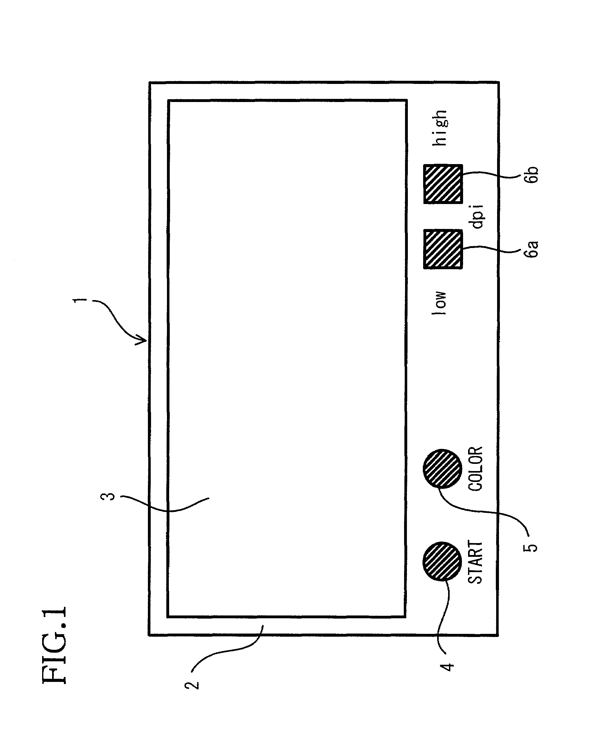
[0014]In the image reading apparatus of the present invention, the predetermined time interval indicated in the second signal generated by the second signal generator may be changed according to the image reading mode selected by the selecting device. Accordingly, a period of an electrical charge accumulating time may freely be changed. The image reading device may be driven at a speed appropriate for the document to be read. When the image is read in high resolutions, the image reading device may be driven at a constant speed slower than a reference speed. At this time, a movement interval of the image reading device may also be changed according to the changes in the predetermined time interval. Therefore, complicated controls for the image reading device are not necessary.
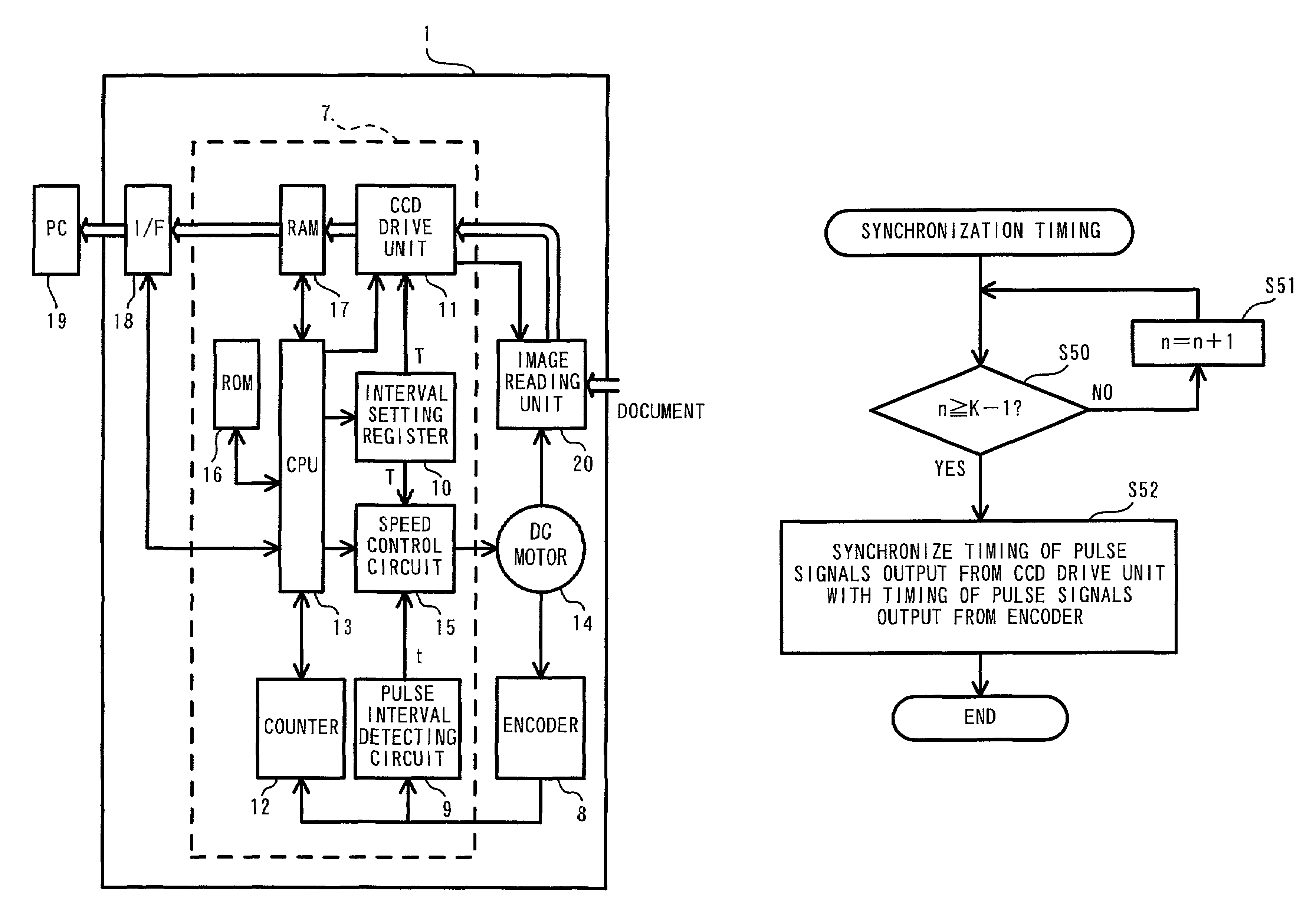
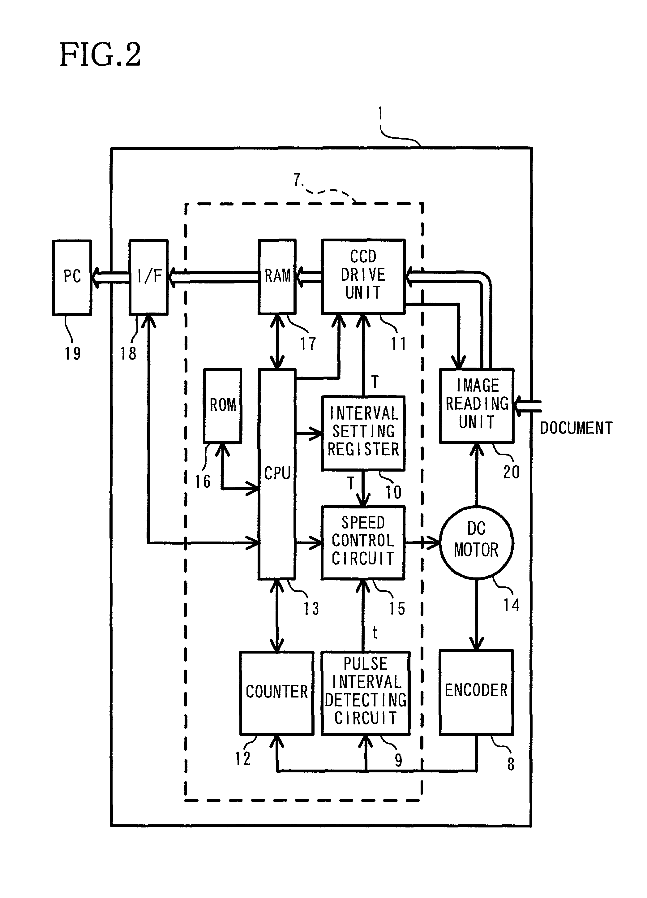
[0016]In the image reading apparatus of the invention, based on the difference between the time interval detected by the signal interval detecting device and the time between the second signals generated by the second signal generator device, the value of current supplied to the driving device may be increased or decreased during image reading operations, so as to conduct drive controls for the image reading device. By synchronizing the moving speed of the driving device with an interval or a period of image reading, the light-receiving time for each line may be kept constant. To start reading the image on the document by the image reading device, the timing to generate the second signal by the second signal generator is synchronized with the timing to generate the first signal by the first signal generator. The electrical charge accumulation start position is, therefore, matched with the image reading start position. Thus, all the distortion, position errors, or misalignment problems in the image data are prevented.
[0017]According to a fourth aspect of the invention, an image reading apparatus includes an interface that connects the image reading apparatus and an external device, a storage device that temporarily stores the image data read by the image reading device before the image data are sent out to the external device through the interface, a detector that detects the amount of available storage space in the storage device, an instruction device that provides an instruction to stop driving the image reading device for the driving device can prevent the image data from being transmitted from the image reading device to the storage device when the detector detects that the image data equal to or greater than a predetermined amount are stored in the storage device. The image reading apparatus also includes a position storage device that stores a position of the image reading device in the scanning direction at a time when the instruction device provides the instruction. After receiving an instruction from the instruction device, the image reading device re-starts to read the image from the position stored in the position storage device when the detector detects that the image data stored in the storage device become equal to or less than a predetermined amount.
[0019]Even when the image reading operations are temporarily stopped to prevent the image data from overflowing from the storage device of the image reading apparatus, the position where the instruction to stop image reading operations is provided, is stored in the position storage device. After the image data stored in the storage device are output to the external device, the electrical charge starts to accumulate from the image reading stop position stored in the position storage device. Therefore, the position errors or misalignment caused by resuming the image reading operations are prevented.

Problems solved by technology

Such variations in the light-receiving time may cause non-uniform electrical charge accumulation in the light-sensitive elements, resulting in irregularity in the electrical charge density.
However, it is difficult for the image reading apparatus to produce the read image as same as the original image of the document.
Therefore, resulting image data becomes improper.
However, the transfer speed of the image data from the image memory to the external device is slower than the speed of the image reading apparatus reading an image.
However, there may be a distance from a position where an instruction to stop the drive system is located to a position where the drive system is actually stopped, or the period from the time when such an instruction is provided to the time the drive system is actually stopped may vary due to the mechanical variations or errors in the driving system.
Therefore, the image reading operations may not be resumed precisely from the stopped position.
Such position errors or misalignment may appear as a gap or an overlap in the read image.

Method used


Image

  • Image reading apparatus
  • Image reading apparatus
  • Image reading apparatus

Examples


Embodiment Construction

[0030]An embodiment of the invention will be described in detail with reference to the drawings.

[0031]FIG. 1 is a schematic illustration of an image reading apparatus 1 according to an embodiment of the present invention. In the embodiment, the image reading apparatus 1 is a flatbed-type image reading apparatus.

[0032]As shown in FIG. 1, the image reading apparatus 1 is provided with a scanner plate 2, a cover 3, and buttons, such as a start button 4 to start reading an image on a document, a color image reading button 5 for switching image reading modes between a color mode and a monochrome mode, a low resolution setting button 6a and a high resolution setting button 6b for changing reading resolutions. The buttons 4, 5, 6a, 6b are provided in a top front surface of the image reading apparatus 1. Each of the buttons 5, 6a, 6b is switched on or off every time the respective button 5, 6a, or 6b is pressed.

[0033]To switch off the low resolution setting button 6a which has been switched...


PUM


Abstract

The invention provides an image reading apparatus that produces a precise image of an original document to prevent the read image from having distortion or irregular density, by driving a DC motor, which drives an image reading unit in a scanning direction, at a constant speed suitable for a document to be read. In addition, the image reading apparatus prevents position errors or misalignment at the start of the image reading, or at a restart of the image reading after the image reading is paused. A speed control circuit provides feedback to a DC motor to synchronize a time interval detected by a pulse interval detecting circuit with a time interval set by an interval setting register, so that the DC motor is operated at a constant speed. A counter counts the number of signals output from an encoder. After the speed of the DC motor is stabilized, a timing of signals output from a CCD drive unit to the image reading unit is synchronized with a timing of the signals generated by the encoder. As a count in the counter reaches a predetermined number, an actual image reading is started. Thus, the position errors or misalignment are prevented in the produced image.

Description

BACKGROUND OF THE INVENTION[0001]1. Field of the Invention[0002]The invention relates to an image reading apparatus, and more particularly, to a scanning control for an image reading unit of the image reading apparatus.[0003]2. Description of the Related Art[0004]A known image reading apparatus reads an image on a document in the following manner. The document placed on a document plate is illuminated with light. An image reading unit includes light-sensitive elements that convert light into electrical charge. The light-sensitive elements are aligned in a main scanning direction. Using a driving device, the image reading unit is moved across the document at a constant speed in a sub scanning direction. The light-sensitive elements of the image reading unit receive the light reflected from the document when the image reading unit is moved by one line. The reflected light received by the light-sensitive elements is converted into electrical charge and output as image data of each line...

Claims


Application Information

Patent Timeline
Patent Type & Authority Patents(United States)
IPC IPC(8): H04N1/04H04N1/047H04N1/10H04N1/107H04N1/21
CPCH04N1/047H04N2201/04731H04N2201/04791H04N2201/04725H04N2201/04734H04N2201/03108H04N2201/04756H04N2201/04786
Inventor YOKOCHI, ATSUSHI
Owner BROTHER KOGYO KK
Why Eureka
Try Eureka