Method and apparatus for a floating well RC triggered electrostatic discharge power clamp

a technology of electrostatic discharge and power clamp, which is applied in the direction of pulse techniques, and emergency protective arrangements for limiting excess voltage/current, etc., can solve the problems of localized overheating at the interface, damage to electronic devices, so as to prevent forward biasing of the body diode

Active Publication Date: 2005-12-06
XILINX INC
View PDF13 Cites 17 Cited by
  • Summary
  • Abstract
  • Description
  • Claims
  • Application Information

AI Technical Summary

Benefits of technology

[0009]To overcome limitations in the prior art, and to overcome other limitations that will become apparent upon reading and understanding the present specification, the present invention discloses a method and apparatus that maintains the bias potential of the bulk region of a resistively coupled transistor to prevent forward biasing of the body diode that is intrinsic to the transistor.

Problems solved by technology

While this sudden discharge of static electricity may be of no harm to human bodies, it can be very damaging to electronic devices which are sensitive to ESD.
Such an ESD event could cause damage to occur in the electronic device due to, for example, localized overheating.
Localized overheating may particularly occur at the interfaces associated with the electronic device, since the interfaces are first to come into contact with the electrostatic discharge.
Although the RC combination is relatively inexpensive, it only limits voltage slew rate, not peak voltage, and produces low pass filter (LPF) distortion, which among other detriments, reduces the maximum data rate possible.
Under some circumstances, however, the shunt device may effect a differential voltage across the transistor, such that the parasitic, or body, diode that is intrinsic to the transistor becomes forward biased.
Once forward biased, a low impedance path is formed through the body diode, whereby the transistor ceases to behave as a resistive component, thus causing a failure in the RC control circuit.

Method used


Image

  • Method and apparatus for a floating well RC triggered electrostatic discharge power clamp
  • Method and apparatus for a floating well RC triggered electrostatic discharge power clamp
  • Method and apparatus for a floating well RC triggered electrostatic discharge power clamp

Examples


Embodiment Construction

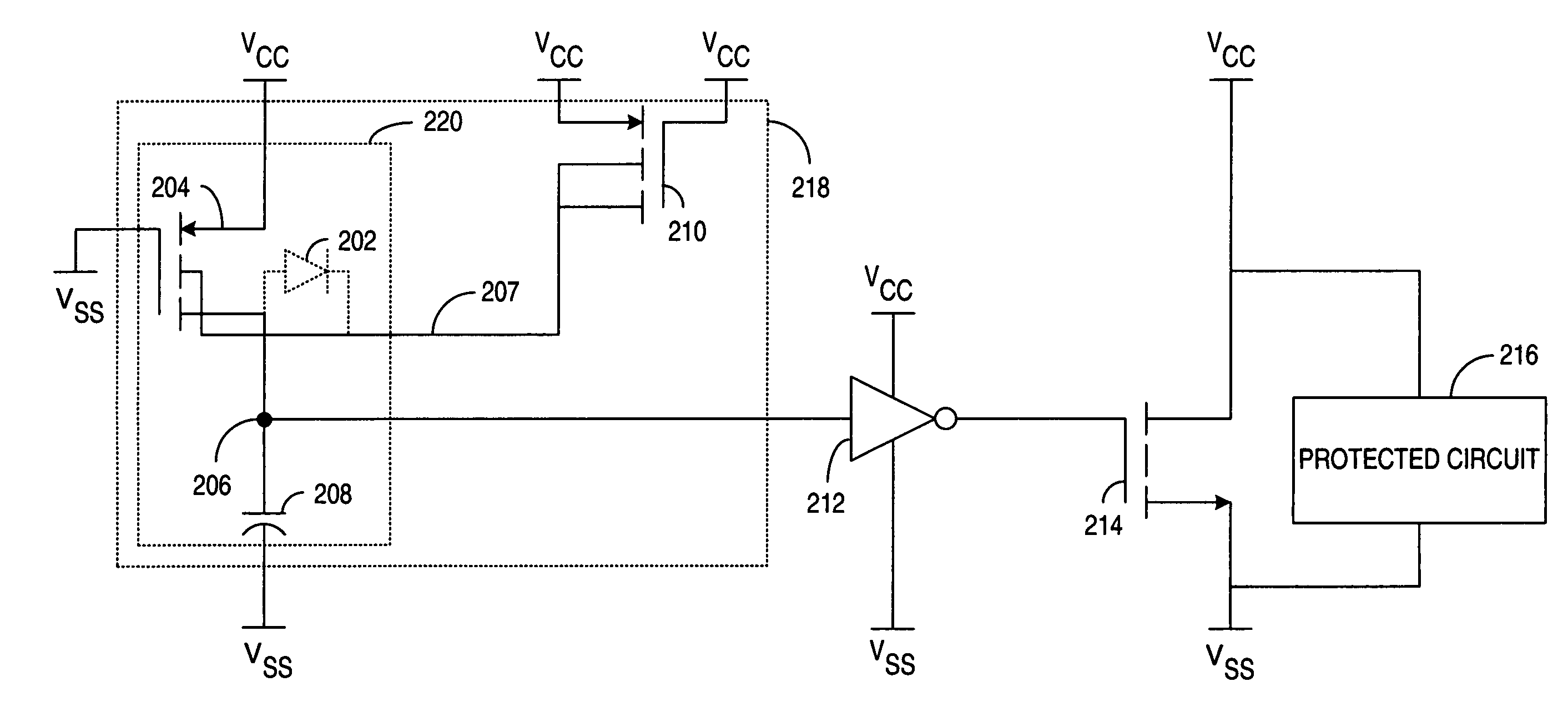
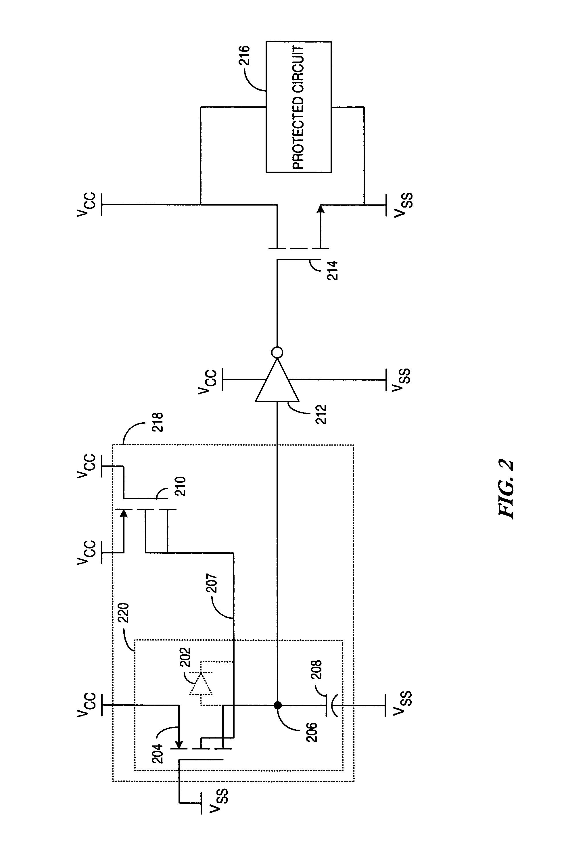
[0020]Various embodiments of the present invention are described in terms of an ESD clamp circuit and associated RC control circuitry. The RC control circuitry of one embodiment of the present invention exhibits protection against forward bias of the parasitic, or body, diode that is intrinsic within a resistively coupled transistor. The resistively coupled transistor being used to realize the resistive component of the RC control circuit. Embodiments of an ESD clamp circuit according to the present invention are shown using complimentary P-type Field Effect Transistor (PFET) and N-type (NFET) topologies. Those skilled in the art will appreciate that the invention could be implemented in other circuit topologies, such as bipolar or bi-Complimentary Metal Oxide Semiconductor (biCMOS), circuit topologies.

[0021]Generally speaking, electrostatic charge associated with an object is stored within a capacitance associated with that object and may accumulate to an extremely high potential. ...


PUM


Abstract

An Electrostatic Discharge (ESD) protection circuit activates an ESD conduction circuit in response to an ESD event. A deactivation circuit generates an exponentially increasing deactivation signal in response to the ESD event, such that once the deactivation signal has increased to a trigger point of a control circuit, the ESD conduction circuit is deactivated. An active resistance component within the deactivation circuit incorporates a biasing element to maintain a resistance value of the active resistance component substantially constant over all operating conditions.

Description

FIELD OF THE INVENTION[0001]The present invention generally relates to Electrostatic Discharge (ESD) protection circuits, and more particularly to ESD protection circuits exhibiting RC trigger circuits that reduce adverse body effects.BACKGROUND[0002]Electrostatic discharge (ESD) is a common occurrence in everyday life. While walking along a carpeted floor in a dry, heated room, for example, enough static electricity is stored within the human body to provide quite a shocking experience when contact is made with another object. Such a contact allows the stored static electricity to suddenly discharge from the human body into the contacted object. While this sudden discharge of static electricity may be of no harm to human bodies, it can be very damaging to electronic devices which are sensitive to ESD.[0003]When an electrostatically charged person or object touches, or comes within sufficient proximity to, an ESD sensitive device, there is a possibility that the electrostatic charge...

Claims


Application Information

Patent Timeline
Patent Type & Authority Patents(United States)
IPC IPC(8): H01L27/02H02H3/22H02H9/00
CPCH01L27/0285H03K2217/0018
Inventor HO, FU-HINGCROTTY, PATRICK J.
Owner XILINX INC
Why Eureka
Try Eureka