Repeater system and method of receiving a modulated input signal and transmitting a modulated output signal

Inactive Publication Date: 2005-12-06
FRAUNHOFER GESELLSCHAFT ZUR FOERDERUNG DER ANGEWANDTEN FORSCHUNG EV
View PDF3 Cites 26 Cited by
  • Summary
  • Abstract
  • Description
  • Claims
  • Application Information

AI Technical Summary

Benefits of technology

[0015]It is the object of the present invention to

Problems solved by technology

Thus, a quite inaccurate repe

Method used


Image

  • Repeater system and method of receiving a modulated input signal and transmitting a modulated output signal
  • Repeater system and method of receiving a modulated input signal and transmitting a modulated output signal
  • Repeater system and method of receiving a modulated input signal and transmitting a modulated output signal

Examples


Embodiment Construction

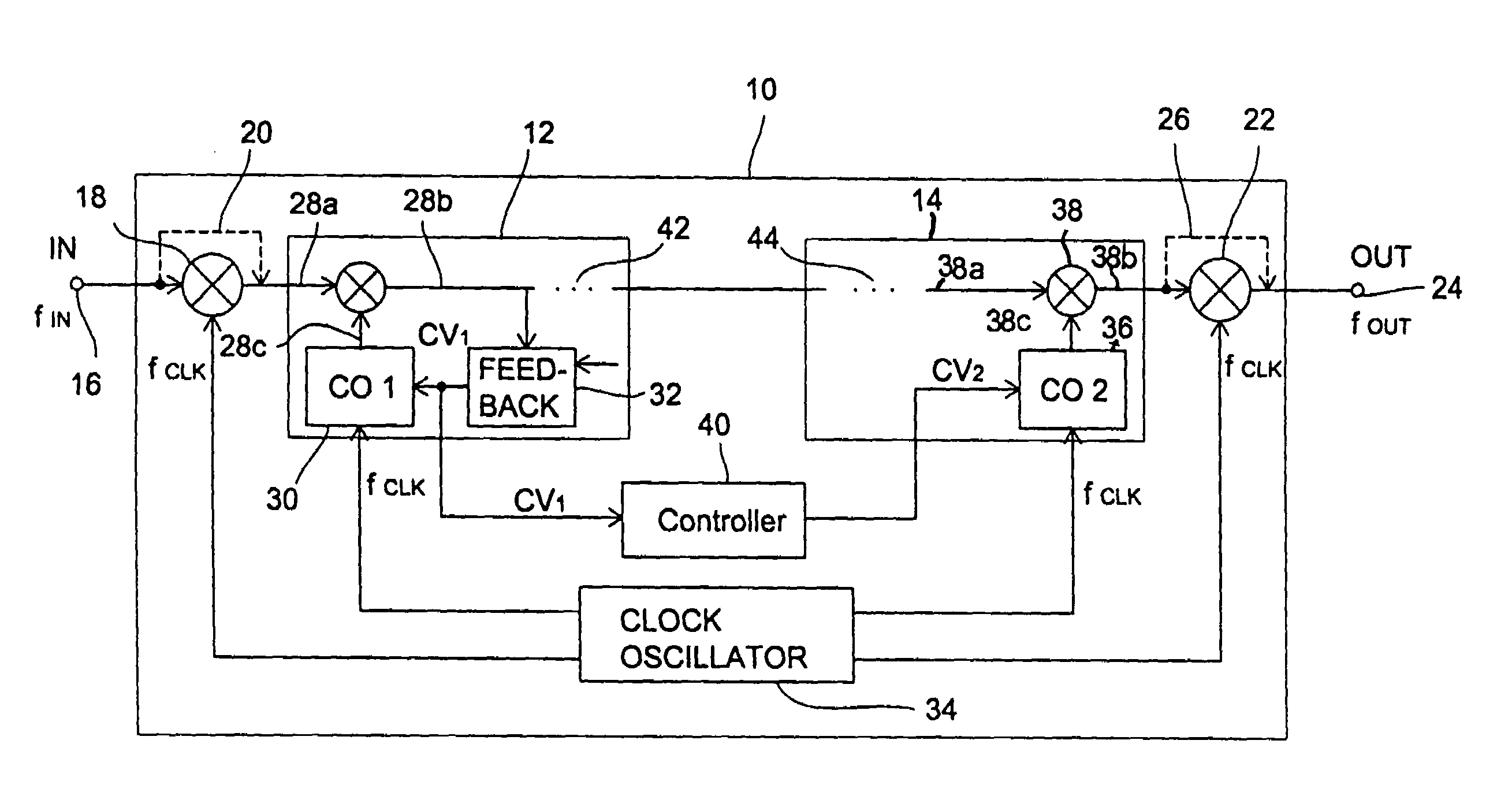
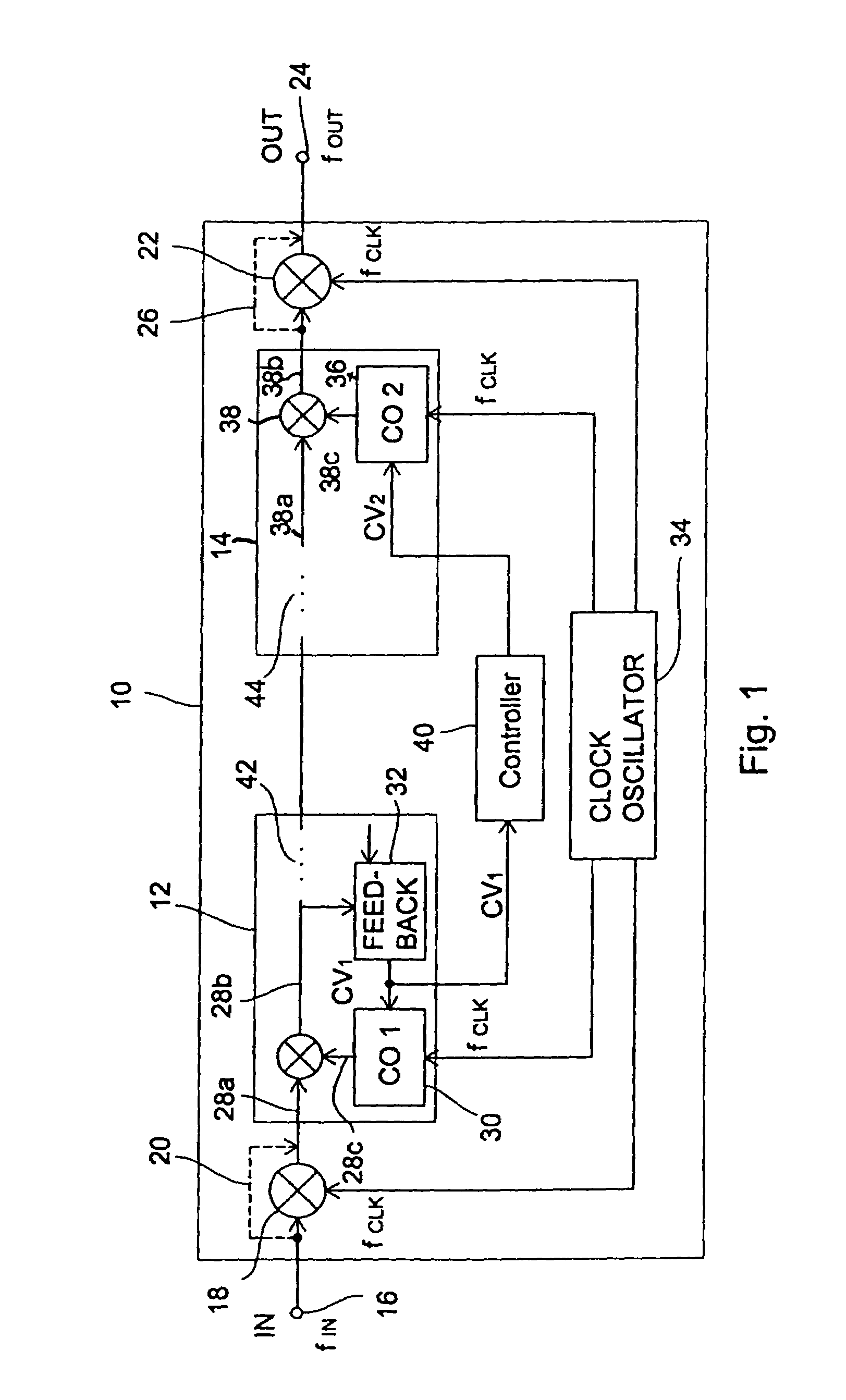
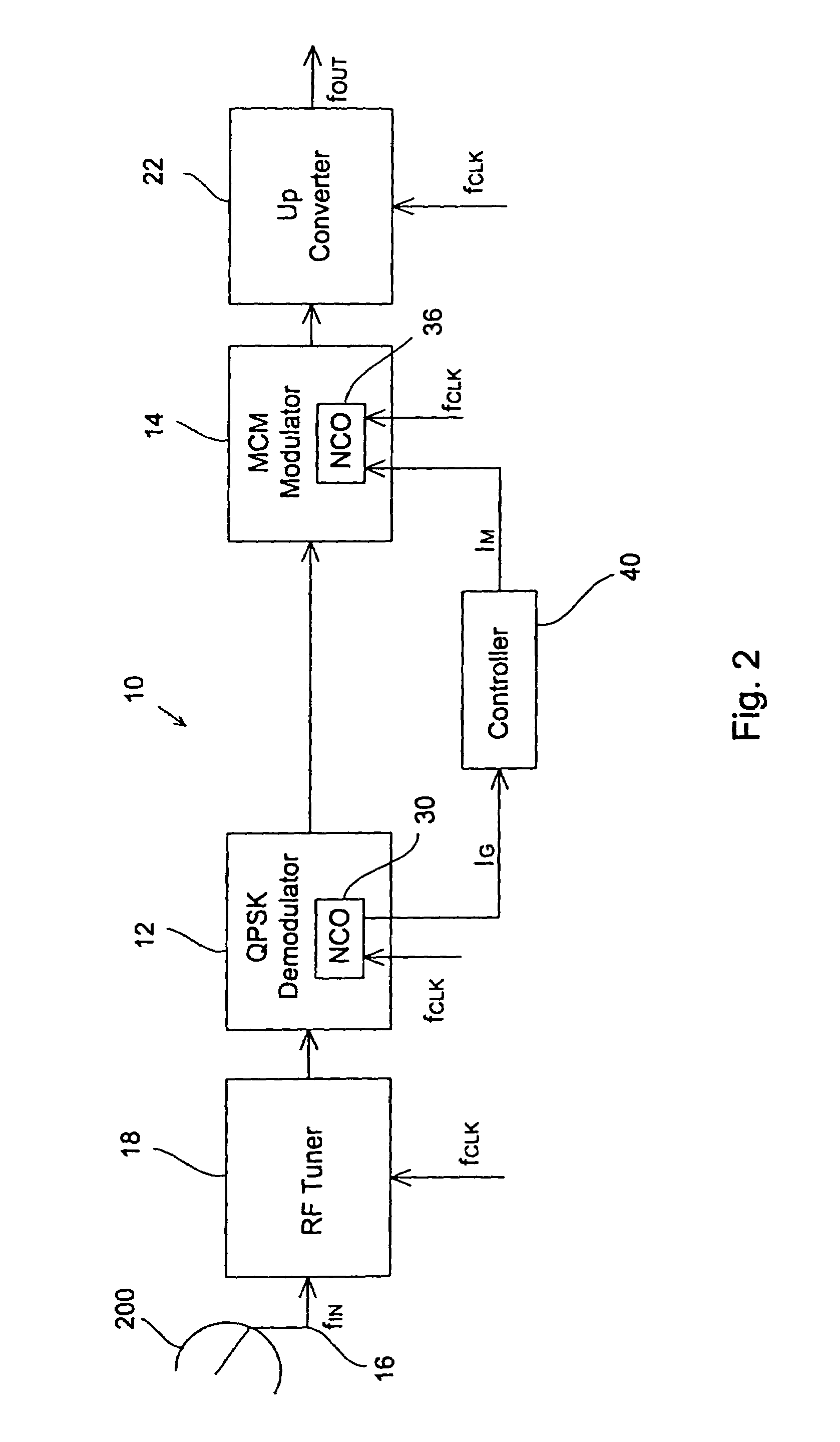
[0027]In FIG. 1, a repeater system in accordance with the present invention which is indicated by the reference numeral 10 is illustrated. The repeater system 10 generally comprises a demodulator 12 and a modulator 14. Connected between an input 16 of the repeater system 10 and an input of the demodulator 12 is a radio frequency (RF) tuner 18, which can optionally be bypassed by a bypass 20. The bypass 20 will be active when the modulated input signal at the input 16 has a frequency fIN which is small enough that the modulated input signal can be processed by the demodulator 12 directly. Similarly, the repeater system 10 comprises an up-converter 22 between an output of the demodulator 12 and an output 24 of the repeater system 10, which can optionally be bypassed by a bypass 26 when the frequency fOUT of the modulated output signal of the repeater system 10 is small enough such that a desired modulated output signal can be generated by the modulator 14.

[0028]The modulator 14 includ...


PUM


Abstract

A repeater system for receiving a modulated input signal and for transmitting a modulated output signal comprising a clock oscillator for providing a repeater system clock, a demodulator for demodulating an input signal and a modulator for modulating the demodulated signal to obtain a modulated signal. The demodulator comprises a first mixer, a first controllable oscillator and a feedback circuit, the first controllable oscillator being controlled by a first control value such that the frequency of the demodulated signal approaches a desired value. The modulator comprises a second mixer and a second controllable oscillator, the second controllable oscillator being controlled by a second control value such that the modulated output signal has a predetermined output frequency. A controller derives the second control value.

Description

BACKGROUND OF THE INVENTION[0001]The present invention relates to a radio transmission system, which comprises a network of transmitters operating with substantially the same carrier frequencies and, in particular, to a repeater system for such a transmission system.[0002]Such transmission system may be used for private networks for transmitting information signals to mobile receivers or for the transmission of several high quality radio programs to a receiving area. Since a high spectral congestion exists, and bandwidths for transmission are very limited, radio transmission systems having a plurality of transmitters, or transmitters operating on substantially the same frequency, have been investigated. Such radio transmission systems are called single frequency networks (SFNs).[0003]However, such systems cause some problems as regarding the reception. One problem is caused by interferences between transmission signals of the same frequency, which are received from several transmitt...

Claims


Application Information

Patent Timeline
IPC IPC(8): H04B7/155H04H20/67
CPCH04B7/15528H04H20/67H04L7/0012
Inventor EBERLEIN, ERNSTBERNHARD, JOSEFPAUL, CHRISTIANVON DER GRUEN, THOMAS
Owner FRAUNHOFER GESELLSCHAFT ZUR FOERDERUNG DER ANGEWANDTEN FORSCHUNG EV
Why Eureka
Try Eureka