High count optical fiber cable

a high-count, optical fiber technology, applied in the direction of optics, fibre mechanical structures, instruments, etc., can solve the problems of difficult identification of any one fiber inside the cable, difficult to produce modules having more than 12, and complicated manufacturing process

Active Publication Date: 2005-12-06
FURAKAWA ELECTRIC NORTH AMERICA INC
View PDF19 Cites 44 Cited by
  • Summary
  • Abstract
  • Description
  • Claims
  • Application Information

AI Technical Summary

Benefits of technology

[0011]In an illustrative embodiment, six fiber bundles are arrayed inside the cable, and the surrounding skins of the bundles are coded for identification. Each fiber bundle includes six cable units the jackets of which are also coded, and each cable unit in turn contains 12 individually coded optical fibers. Thus, a total of 432 fibers are enclosed in the cable in such a manner that any one of the fibers can be easily accessed as desired.

Problems solved by technology

Since it is difficult and costly to produce modules having more than 12 fibers each, a cable with a fiber count greater than 216 must accommodate more than 18 of such modules in a unitary configuration.
This constraint makes the manufacturing process quite complex.
Further, the identification of and access to any one fiber inside the cable becomes difficult.

Method used


Image

  • High count optical fiber cable
  • High count optical fiber cable
  • High count optical fiber cable

Examples


first embodiment

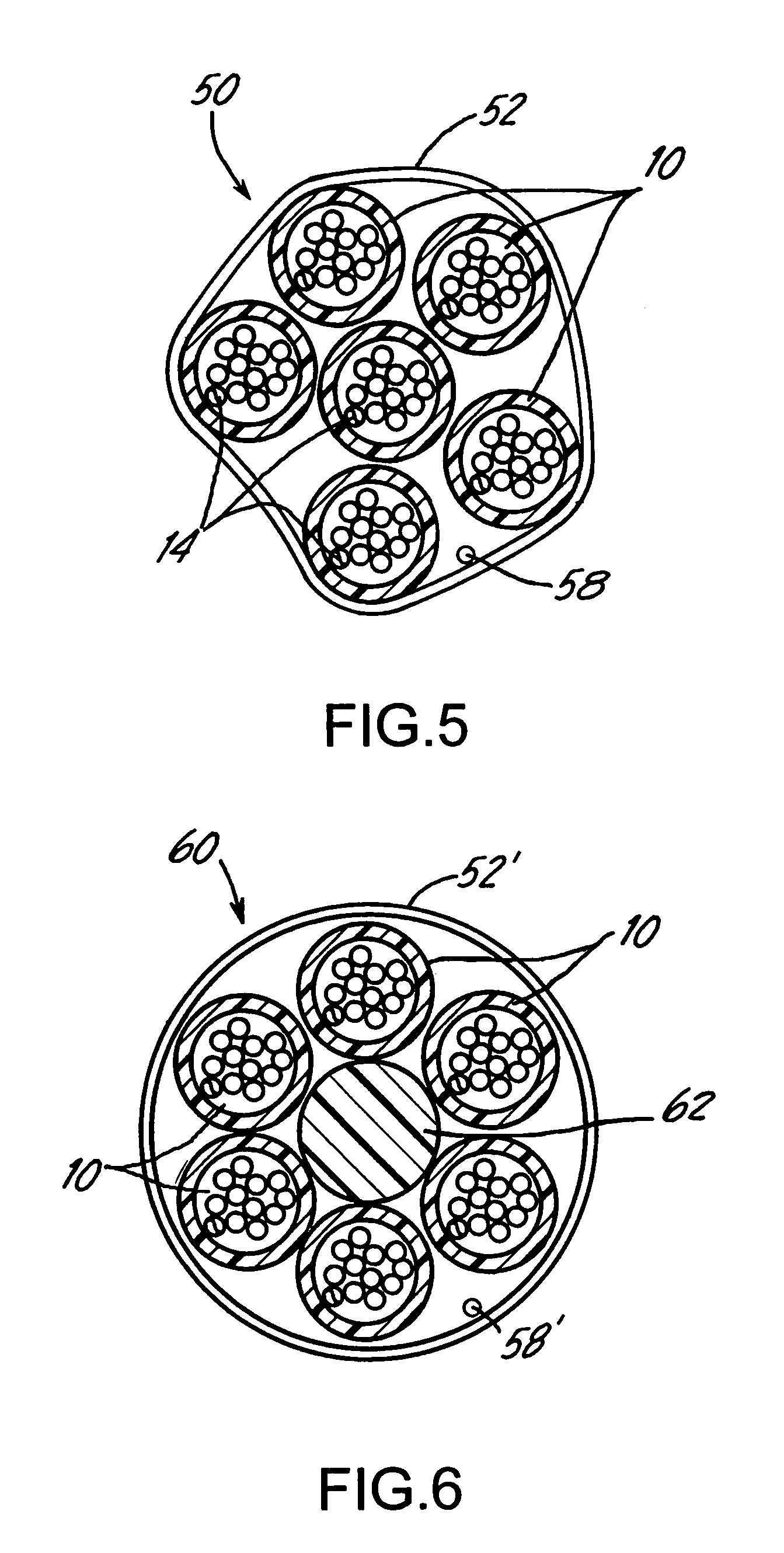
[0033]FIG. 7 is a cross-sectional view of a 432-optical fiber cable core 70, according to the invention. The cable core 70 includes six of the 72-fiber bundles 50 shown in FIG. 5. The thin skins 52 of each bundle may be coded by color and / or marking indicia to permit location of and access to a desired one of the cable units 10 contained in the bundle. All of the fiber bundles 50 are contained within a core tube 72 having an outer diameter of, e.g., about 0.74 inch (18.76 mm) and an inner diameter of, e.g., about 0.60 inch (15.24 mm). The core tube 72 is preferably made of plastics such as, e.g., polyethylene with a wall thickness of about 0.035 inch (0.89 mm). The cable core 70 in FIG. 7 lacks any filler element, and is packed with water swellable yarns 74 and has a layer of water swellable tape 76 on the inner circumference of the core tube 72. Water ingress along each of the bundles 50 may also be prevented by introducing a super absorbent powder over the bundle skins 52.

second embodiment

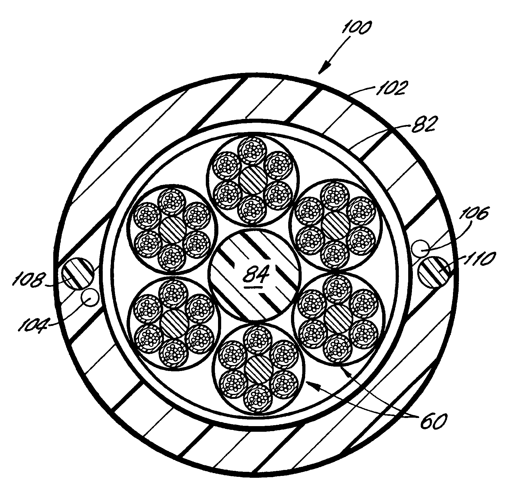
[0034]FIG. 8 is a cross-sectional view of a 432-optical fiber cable core 80 according to the invention. The cable core 80 is comprised of a core tube 82 which may be the same or similar to the core tube 72 in FIG. 7. Unlike the FIG. 7 embodiment, however, the cable core 80 maintains an even or symmetrical configuration of the six 72-fiber bundles 60 in FIG. 6 with the aid of a filler element 84. The element 84 extends along the length of the cable core substantially coincident with the core axis. The skins 52 of the fiber bundles 60 are also preferably coded by color and / or marking indicia to facilitate identification of a given fiber among the 36 cable units inside the core. Voids between the individual bundles 60 and the core tube 82 may be packed with yarns (not shown), and a layer of water blocking tape 86 may be provided on the inner circumference of the core tube 82 to reduce or eliminate moisture. The core tube 82 may be formed using the same material and dimensions as the tu...

third embodiment

[0035]FIG. 9 is a cross-sectional view of a 432-fiber cable core 90 according to the invention. The configuration shown in FIG. 9 is a so-called central core cable construction, and includes a core tube 92 and three fiber bundles 94 each of which contains twelve of the cable units in FIG. 1. Each bundle 94 may have a different colored thin skin 96 of polypropylene with a thickness of about 0.008 inch. The outer diameter of the core tube 92 is about 0.72 inch (18.3 mm) and the outer diameter of each of the fiber bundles 94 is about 0.26 inch (6.6 mm). Each of the fiber bundles 94 thus contains 144 optical fibers any given one of which can be identified and accessed by appropriate coding and the use of multiple rip cords. As in the embodiments described above, voids between the individual bundle skins 96 and the inside surface of the core tube may be packed with yarns (not shown), and a layer of water blocking tape 98 may be placed on the inside surface of the tube 92 to reduce or eli...


PUM


Abstract

An optical fiber cable includes a number of optical fiber bundles. Each bundle contains a number of optical fiber cable units, and a relatively thin skin surrounds the cable units and retains the units in a desired configuration another over the length of the bundle. Each cable unit includes a number of optical fibers, and a first outer jacket that surrounds the fibers. The bundles are protectively enclosed by a second outer jacket of the cable. In an illustrated embodiment, each cable unit has 12 fibers, each bundle contains 12 cable units, and six bundles are protectively enclosed by the second outer jacket, so that the cable contains 432 optical fibers each of which is traceable by color and / or indicia markings.

Description

BACKGROUND OF THE INVENTION[0001]1. Field of the Invention[0002]This invention relates to telecommunication cable construction, and particularly to a cable configuration that accommodates a large number of optical fibers.[0003]2. Discussion of the Known Art[0004]Optical fibers for communication and information networks may be supplied individually wherein a buffer layer of soft plastics material covers the cladding of each fiber, and a hard outer layer around the buffer layer protects the fiber from the environment. Fibers may also be provided in the form of a “loose tube” cable in which fibers are contained loosely inside one or more flexible hollow tubes that are surrounded by a cable jacket, thus avoiding undue stress on the fibers while the cable is being handled during installation or servicing in the field.[0005]Loose tube cables may also include a central dielectric member that provides rigidity to the cable, and acts as a solid core about which the individual fibers may be c...

Claims


Application Information

Patent Timeline
Patent Type & Authority Patents(United States)
IPC IPC(8): G02B6/44
CPCG02B6/441
Inventor BOCANEGRA, LUIS M.DEBBAN, JR., HAROLD P.
Owner FURAKAWA ELECTRIC NORTH AMERICA INC
Why Eureka
Try Eureka