Image forming apparatus

a technology of image forming apparatus and photoconductor drum, which is applied in the direction of electrographic process apparatus, instruments, optics, etc., can solve the problems of high cost, difficult to make uniform the pressing balance of the photoconductor drum, and inability to obtain high-quality printed images, etc., and achieve the effect of stably providing electric power

Active Publication Date: 2005-12-06
PANASONIC CORP
View PDF12 Cites 38 Cited by
  • Summary
  • Abstract
  • Description
  • Claims
  • Application Information

AI Technical Summary

Benefits of technology

[0026]According to this arrangement, the distal end of the main body-side conductive member and the connecting slot member of the coil spring are fitted in the connecting slot member, and are thereby electrically connected to each other. Therefore, their respective free movement is restricted by the connecting slot member, and the state of their mutual contact is stabilized, making it possible to stably supply electric power from the electric supply means to the charger.

Problems solved by technology

Therefore, it becomes difficult to make uniform the pressing balance of the photoconductor drums 2a to 5a with respect to the intermediate transfer belt 7.
Hence, a difference in density occurs in the developed toner image, so that it is impossible to obtain a high-quality printed image.
However, in the above-described construction, the number of component parts ranging from the electric supply means to the charger becomes numerous, resulting in higher cost.
In that event, noise can occur due to friction during movement, thereby rendering stable supply of electricity impossible.

Method used


Image

  • Image forming apparatus
  • Image forming apparatus
  • Image forming apparatus

Examples


first embodiment

[First Embodiment]

[0045]Referring now to FIGS. 1 to 4, a description will be given of an embodiment of the invention. It should be noted that in these drawings identical members will be denoted by the same reference numerals, and that a redundant description thereof will be omitted.

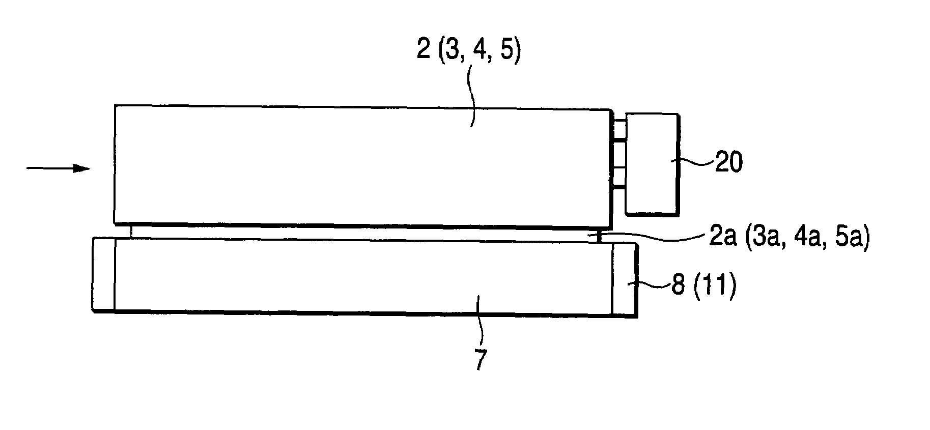
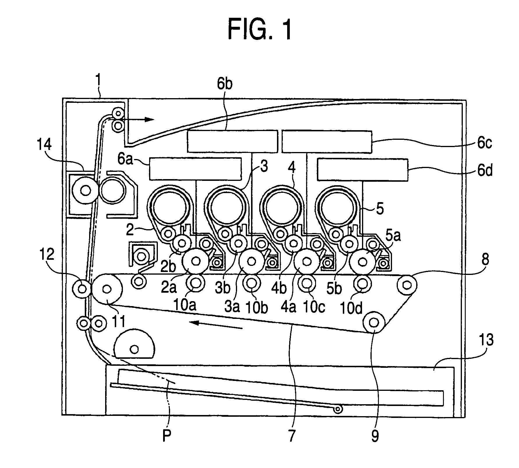
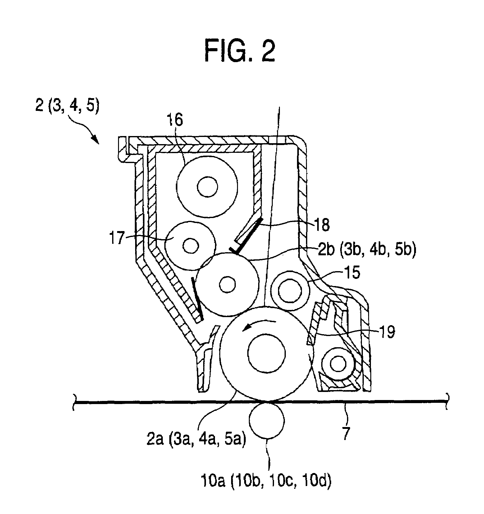
[0046]FIG. 1 is a schematic diagram illustrating the construction of a color image forming apparatus in accordance with the embodiment of the invention. FIG. 2 is an explanatory diagram illustrating in detail image forming units in the color image forming apparatus shown in FIG. 1. FIG. 3 is a perspective view illustrating in extracted form a high-voltage unit, an intermediate transfer belt, and the image forming units in the color image forming apparatus shown in FIG. 1. FIG. 4 is an explanatory diagram illustrating the positional relationship among the image forming units, the high-voltage unit, and the intermediate transfer belt in a state in which the image forming units are installed in the color ima...

second embodiment

[Second Embodiment]

[0062]Referring next to FIGS. 5 to 14, a description will be given of a more detailed construction of the above-described first embodiment as a second embodiment of the invention. Those component parts that are substantially identical to those of the first embodiment will be denoted by the same reference numerals, and a redundant description thereof will be omitted.

[0063]As shown in FIGS. 5 and 6, the photoconductor drum 5a, the developing roller 5b, the charging roller 15, the supply roller 17, a developing-roller biasing metal sheet 105, and a supply-roller biasing metal plate 117 are provided at an end portion of the image forming unit 5 for black on the side away from a grip portion 55. An end portion of the charging roller 15 is in electrical contact with the high-voltage unit 20, and corresponds to one of the terminals 22 in the above-described first embodiment. The developing-roller biasing metal sheet 105 is also in electrical contact with the high-voltage...

third embodiment

[Third Embodiment]

[0074]FIG. 17 is a perspective view illustrating a peripheral structure of the charging means provided in the color image forming apparatus shown in FIG. 1.

[0075]Here, as shown in FIG. 17, the charger 15 is supported by a conductive bearing 720. A coil spring 722 is in pressure contact with the bearing 720, so that the charger 15 is pressed against each of the photoconductor drums 2a to 5a through the bearing 720 by the resiliency of the coil spring 722 acting on the bearing 720.

[0076]A connecting end portion 722a of the coil spring 722 is formed in such a manner as to extend like a rod formed substantially in an L-shape. A main body-side conductive member 721 for carrying electric power from an electric supply means (not shown) abuts against this connecting end portion 722a to electrically connect the two members.

[0077]As shown in the drawing, a distal end of the main body-side conductive member 721 is fitted in a connecting slot member 723 formed in the shape of ...


PUM


Abstract

An image forming apparatus includes: image forming units provided detachably and each having a developing roller for supplying a toner to an electrostatic latent image formed on a charged photoconductor drum to form the electrostatic latent image into a visible image; an endless intermediate transfer belt which is provided in such a manner as to be capable of abutting against the photoconductor drum and is adapted to rotate in loop form by being supported in a tension-adjusted state by a plurality of rollers, and onto which a toner image developed on the photoconductor drum is transferred; and a high-voltage unit which is electrically and mechanically connected to the image forming units through terminals to supply predetermined electric power to the photoconductor drums, chargers, and the developing rollers of the image forming units. The image forming units are arranged to be moved in a width wise direction of the intermediate transfer belt so as to be connected to the high-voltage unit.

Description

BACKGROUND OF THE INVENTION[0001]The present invention relates to an image forming apparatus.[0002]In an image forming apparatus adopting the electrophotographic process, it has conventionally been practiced to charge a photoconductor, i.e., an image carrier, with a charger, form a latent image by irradiating the charged photoconductor with light corresponding to image information, develop this latent image by a developing unit, and transfer the developed toner image onto a recording medium, so as to form an image.[0003]On the other hand, in conjunction with a trend toward the coloring of images, a color image forming apparatus of a tandem type has also been proposed. This color image forming apparatus of this type has a plurality of image forming units which perform such image forming processes. Toner images of the respective colors of a cyan image, a magenta image, a yellow image and preferably a black image are formed on respective photoconductors. These toner images are subseque...

Claims


Application Information

Patent Timeline
Patent Type & Authority Patents(United States)
IPC IPC(8): G03G21/18
CPCG03G21/185G03G21/1867G03G2215/0119G03G2221/166
Inventor MIZOGUCHI, YOSHIHIRO
Owner PANASONIC CORP
Why Eureka
Try Eureka