Semiconductor mechanical quantity sensor

Inactive Publication Date: 2005-12-13
DENSO CORP
View PDF7 Cites 7 Cited by
  • Summary
  • Abstract
  • Description
  • Claims
  • Application Information

AI Technical Summary

Benefits of technology

[0009]The above constitution makes it possible to improve the sensitivity by a plurality of number of times without causing sticking.
[0010]When the output of a single sensor is doubled, the noise component, too, is doubled and the S/N ratio does not vary.

Problems solved by technology

However, the resilient restoring force 1 and the mov

Method used


Image

  • Semiconductor mechanical quantity sensor
  • Semiconductor mechanical quantity sensor
  • Semiconductor mechanical quantity sensor

Examples


Example

[0019]An embodiment of the invention will now be described with reference to the drawings.

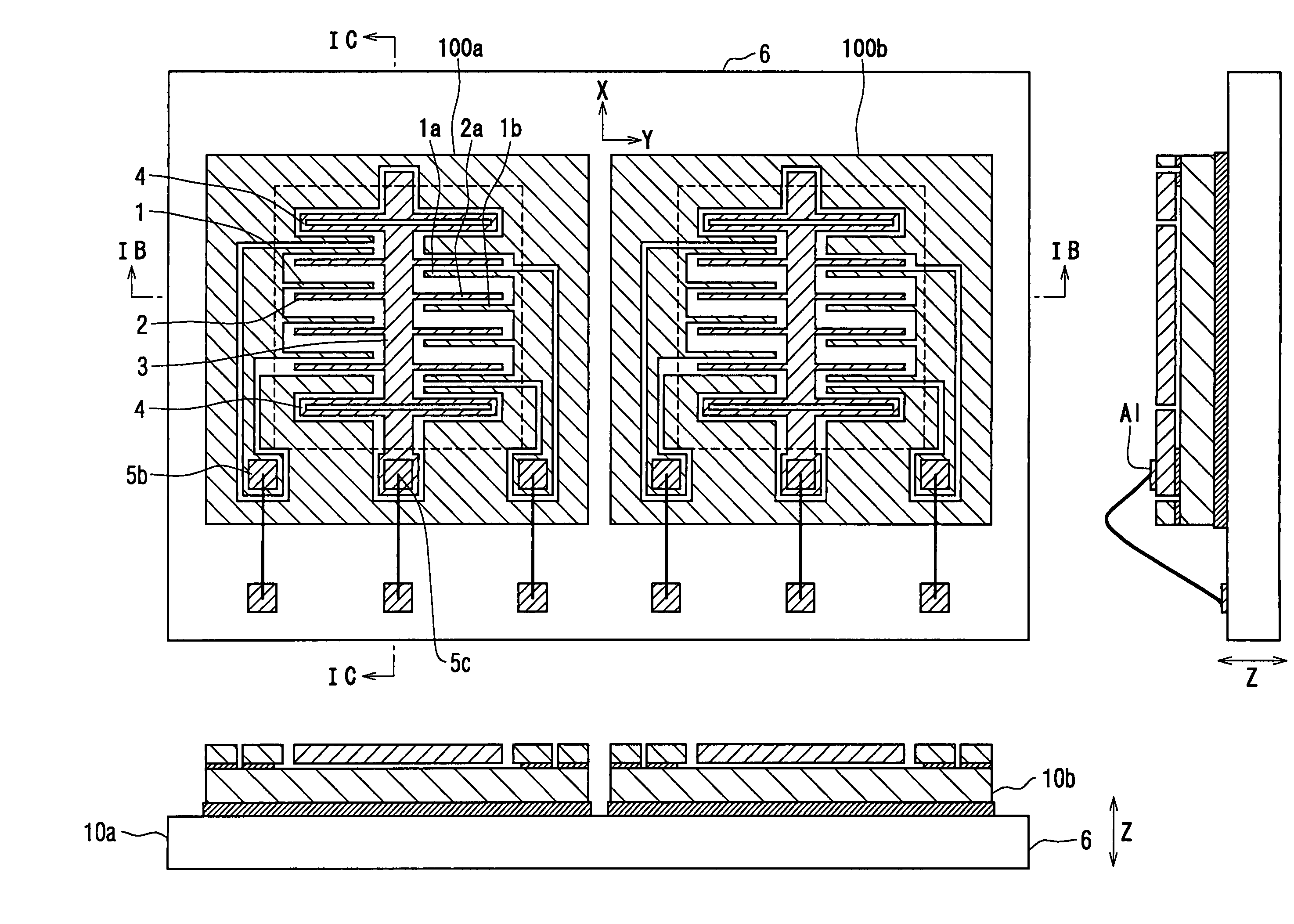
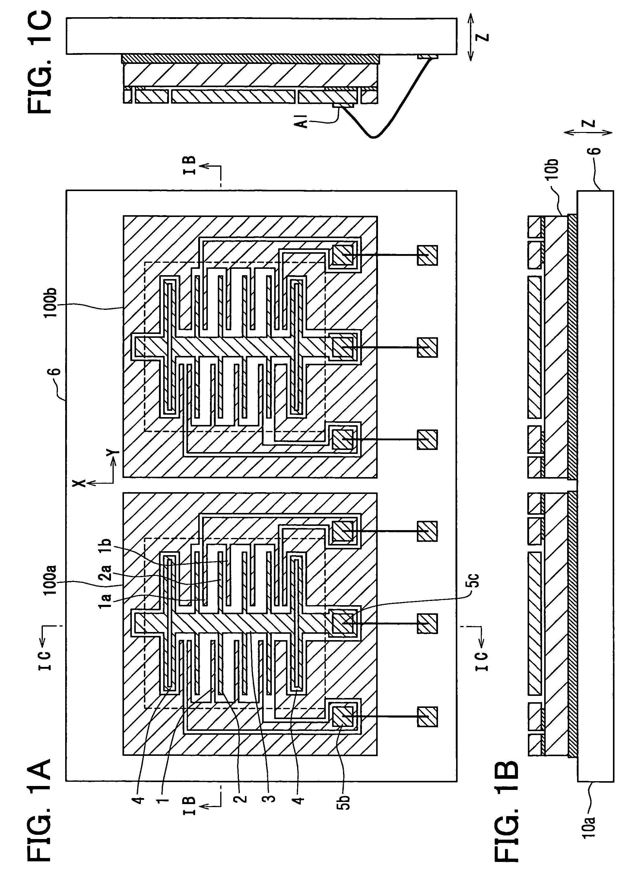
[0020]FIGS. 1A–1C illustrate an embodiment in which two sensor chips 100a and 100b, which have the same structure and the same characteristics, are formed in semiconductor substrates 10a and 10b and are arranged in the same direction on a circuit chip 6. The electrodes 1 and 2, weight 3 and beams 4 constituting the sensor chips 100a and 100b have conventional structures and will not be described here in detail.

[0021]Here, if the capacitance between the electrodes 1 and 2 is denoted by C0, the spring constant of the beams 4 by k, the mass by m, and the distance between the electrodes 1 and 2 by d, then the sensitivity may be defined as follows:

Sensitivity∝C0·k / m

[0022]Further, the resilient restoring force of the beams 4 is expressed by ∝k, the electrostatic force between the electrodes 1 and 2 is expressed by ∝0.5·C0·V2 / d, the Z-direction displacement of the moving electrode 1 is expressed by ∝(...


PUM


Abstract

A semiconductor mechanical quantity sensor includes two sensor chips (100a, 100b) having the same structure and the same characteristics formed on semiconductor substrates (10a, 10b), arranged on a circuit chip (6) in the same direction. There may be used a sensor chip having two sensors of the same structure formed in one semiconductor substrate in the same direction. The number of the sensors may be three or more. A plurality of sensors may be stacked on the semiconductor substrate or on the circuit chip, or may be arranged on both surfaces of the semiconductor substrate (10a, 10b) or the circuit chip (6).

Description

CROSS REFERENCE TO RELATED APPLICATIONS[0001]This application is based upon, claims the benefit of priority of, and incorporates by reference the contents of Japanese Patent Application No. 2003-65836 filed on Mar. 12, 2003.FIELD OF THE INVENTION[0002]This invention relates to a semiconductor mechanical quantity sensor for detecting the mechanical quantity such as acceleration based on the capacities among fixed electrodes and moving electrodes.BACKGROUND OF THE INVENTION[0003]A semiconductor mechanical quantity sensor has been disclosed in, for example, JP-A-5-304303. A mono-axial (X-direction) capacitor-type acceleration sensor will be generally described with reference to FIGS. 3A–3C. Grooves 11 are formed in a semiconductor layer of a semiconductor substrate 10 such as of silicon, whereby a plurality of pairs of fixed electrodes 1 and moving electrodes 2 are opposed to each other in the X-direction to constitute capacitors. The moving electrodes 2 are formed in a plurality of pa...

Claims


Application Information

Patent Timeline
IPC IPC(8): B81B7/04G01P15/125H01L29/84
CPCG01P15/125B81B7/04G01P2015/0814
Inventor SAKAI, MINEKAZU
Owner DENSO CORP
Why Eureka
Try Eureka