Valve controlled fluidic actuator system

Inactive Publication Date: 2005-12-13
FESTO AG & CO KG
View PDF31 Cites 11 Cited by
  • Summary
  • Abstract
  • Description
  • Claims
  • Application Information

AI Technical Summary

Benefits of technology

[0004]One object of the present invention is to provide a valve controlled fluid power actuator arrangement in which the valve arrangement is positioned separated in space from the actuator arrangement and in which the plastic li

Problems solved by technology

Owing to the electrical line strands in the plastic line

Method used


Image

  • Valve controlled fluidic actuator system
  • Valve controlled fluidic actuator system
  • Valve controlled fluidic actuator system

Examples


Example

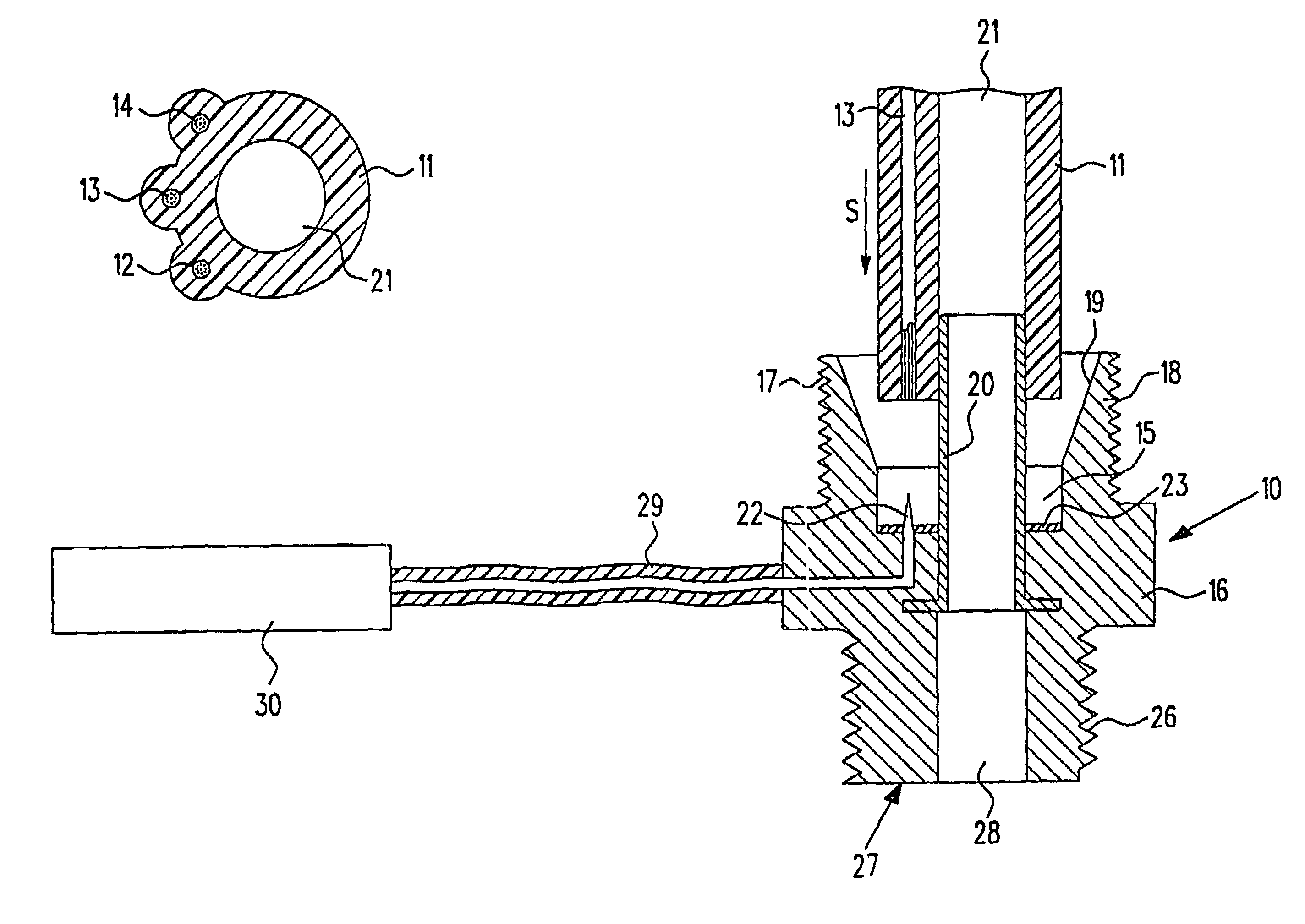
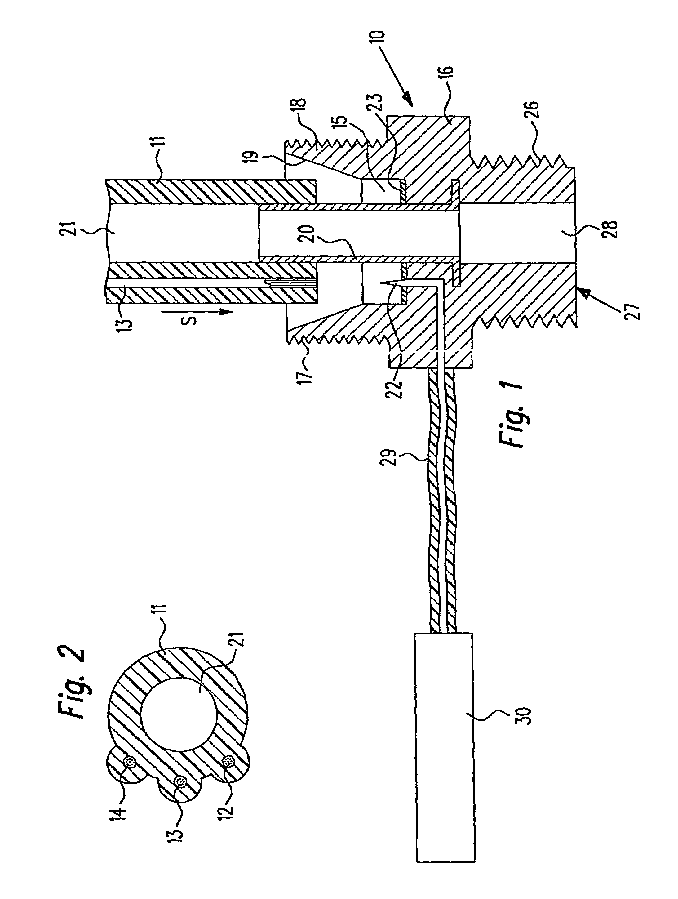
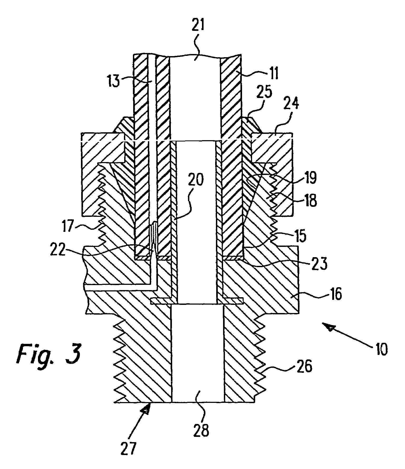
[0025]The connection member 10 illustrated in FIGS. 1 and 3 serves essentially for connection with a flexible plastic fluid power line 11, in whose wall three electrical line strands 12 through 14 extend which for instance are in the form of fine flexible wires. The number of the line strands 12 through 14 is naturally able to be selected freely between one and a plurality of line strands.

[0026]The plastic line 11 possesses a non-radially symmetrical cross section so that insertion into a line connection socket 15 with a matching cross section of the principal body 16 of the connection member is only possible in a predetermined angular position. The line connection socket 15 is in this case surrounded by a tubular wall portion 18, having an external screw thread 17, of the principal body 16. A part of the wall portion 18 adjacent to the part with the line connection socket 15 is tapered toward its axial end so that at its internal side a circularly conical oblique face 19 is formed....


PUM


Abstract

A valve controlled fluid power actuator arrangement having a fluid power valve arrangement (61) controlled by an electronic control means (63 through 65) being connected by means of at least one plastic fluid power line (11) with at least one actuator (62). In the plastic line (61) electrical line strands and/or light guides are integrated for the transmission of sensor signals. The at least one plastic line (11) is connected with the respective actuator (62) with the aid of a connection member (10) having a connection cable (29) with at least one sensor (30) in or on the actuator (62). Accordingly in the case of a valve arrangement separate from the actuators a rapid and simple fluid power and electrical or, respectively, optical assembly may take place.

Description

[0001]This application is the National Stage of PCT Application No. PCT / EP01 / 12012 filed on Oct. 17, 2001 which claims priority to German Application No. 100 54 561.0 filed on Oct. 31, 2000.FIELD OF THE INVENTION[0002]The invention relates to a valve controlled fluid power actuator arrangement comprising a fluid power valve arrangement controlled by an electronic control means plastic fluid power lines being provided having integrated line strands and / or light guides for the transmission of sensor signals.BACKGROUND OF THE INVENTION[0003]The European patent publication 0803653 A1 discloses an arrangement, in which the transmission of the working pressure and of sensor signals from position sensors to power cylinders takes place by way of electropneumatic plastic lines. In this case the electropneumatic plastic lines are connected by way of connection members with valve arrangements, which are arranged on the power cylinders. The position sensors are connected by way of electrical li...

Claims


Application Information

Patent Timeline
IPC IPC(8): F15B15/20G08C23/04F15B15/28F15B21/08F16L19/065F16L25/01
CPCF15B15/202F15B15/2807F15B21/08F16L19/0653F16L25/01
Inventor FRISCH, HERBERTBECK, WILFRIED
Owner FESTO AG & CO KG
Why Eureka
Try Eureka