Work sheet conveying device

a conveying device and work sheet technology, applied in the direction of metal-working feeding device, transportation and packaging, manufacturing tools, etc., can solve the problems of difficulty in increasing the speed of the traveling member and reducing the time required for acceleration and deceleration, so as to improve the efficiency, improve the speed of the conveying of work sheets, and reduce the time required

Inactive Publication Date: 2008-10-30
MURATA MASCH LTD
View PDF15 Cites 4 Cited by
  • Summary
  • Abstract
  • Description
  • Claims
  • Application Information

AI Technical Summary

Benefits of technology

[0006]An object of the present invention is to solve the above-described problems to provide a work sheet conveying device having a traveling member with a compact work sheet holder, making it possible to improve work sheet conveying speed and to reduce the time required for acceleration and deceleration, the work sheet conveying device further making it possible to improve the efficiency with which small work sheets are conveyed. Another object of the present invention is to make it possible to easily switch between a state in which work sheet holders of a plurality of traveling members hold the same work sheet and a state in which the work sheet holder of each of the traveling members individually holds a work sheet. Yet another object of the present invention is to, where the work sheet holders of the plurality of traveling members hold the same work sheet, allow the work sheet holders to hold as large a work sheet as possible.

Problems solved by technology

With the large-scale work sheet holder, the weight of the device itself makes it difficult to increase the speed of the traveling member and to reduce the time required for acceleration and deceleration.

Method used


Image

  • Work sheet conveying device
  • Work sheet conveying device
  • Work sheet conveying device

Examples


Embodiment Construction

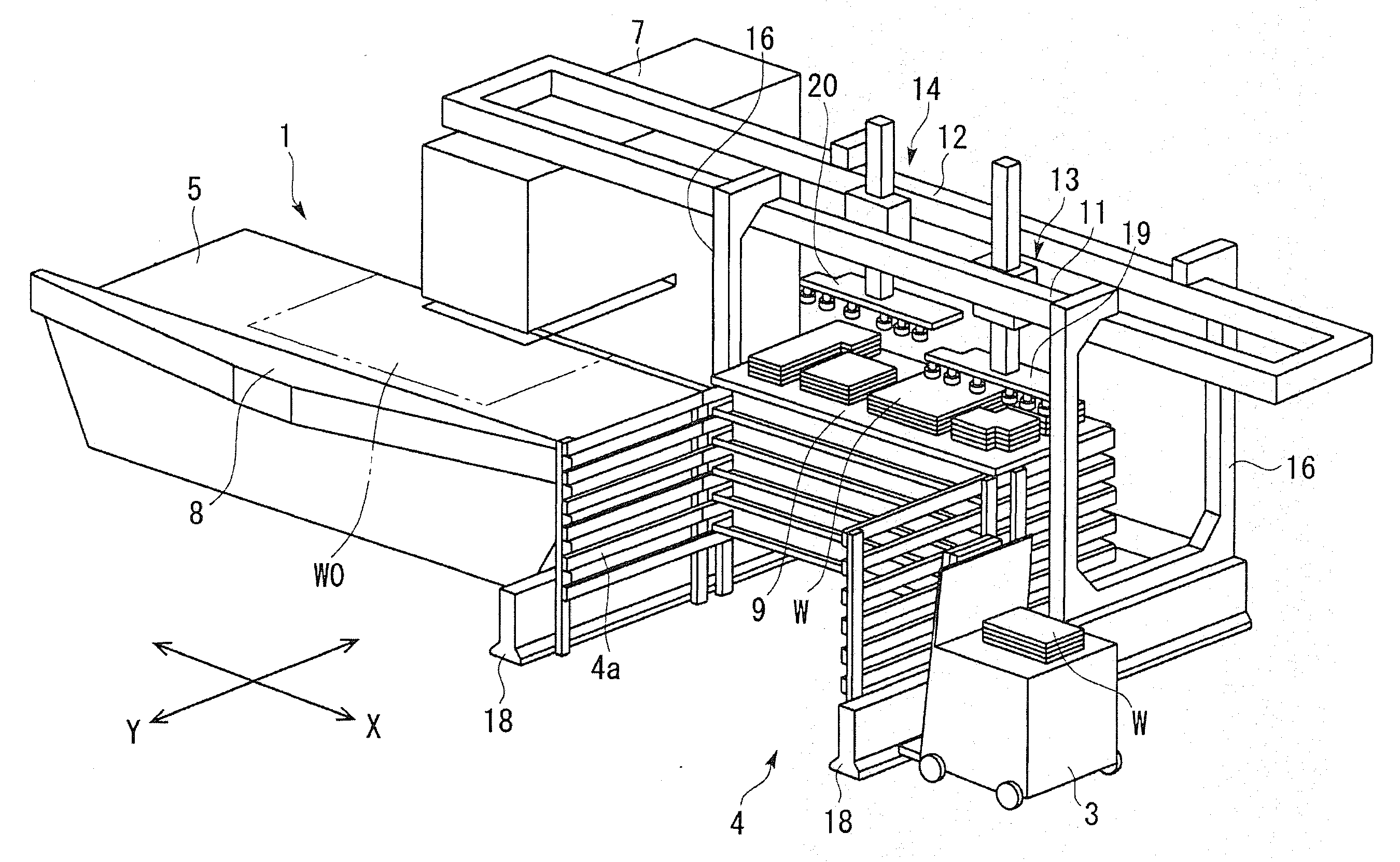
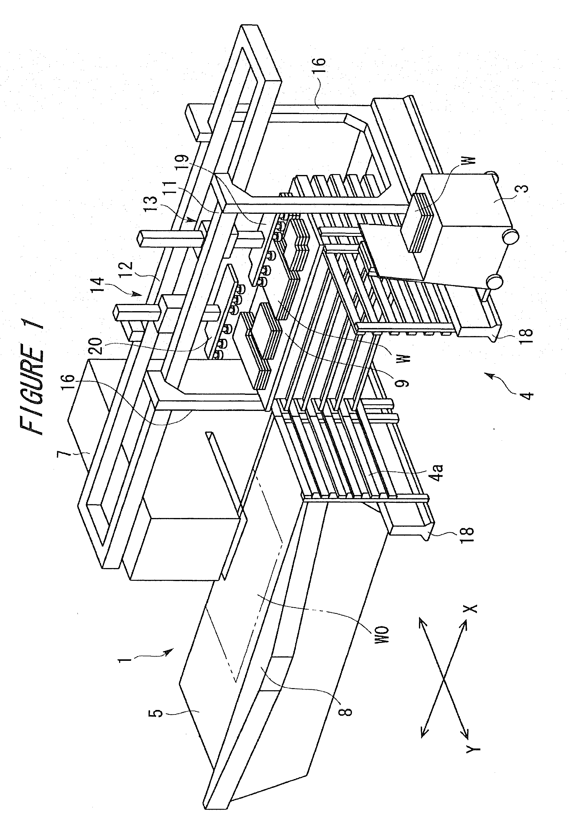
[0020]An embodiment of the present invention will be described with reference to FIGS. 1 to 4. FIG. 1 is a perspective view of an entire work sheet processing system comprising a work sheet processing machine 1, a work sheet conveying device 2, a palette 9 and a work sheet transporting vehicle 3 which serve as a work sheet placement portion, and a work sheet stocker 4. The work sheet processing system further comprises a work sheet carry-in device (not shown in the drawings) that carries a material work sheet WO into the work sheet processing machine 1. However, the description of the work sheet carry-in device is omitted.

[0021]The work sheet processing machine 1 comprises a function of cutting a plurality of product work sheets W from the material work sheet WO on a table 5 by means of punching or the like. The work sheet processing machine 1 is composed of a punch press, a laser processing machine, or the like. In this example, the work sheet processing machine 1 is a punch press ...


PUM


Abstract

The present invention provides a work sheet conveying device having a traveling member with a compact work sheet holder, making it possible to improve work sheet conveying speed and to reduce the time required for acceleration and deceleration, the work sheet conveying device further making it possible to improve the efficiency with which small work sheet's are conveyed. The work sheet conveying device includes a plurality of traveling members 13, 14 that can travel independently along a plurality of tracks 11, 12 installed parallel to one another between a work sheet processing machine 1 and a work sheet placement portion. Each of the traveling members has a work sheet holder 19, 20 that holds a work sheet. A part of the work sheet holder 19, 20 is configured as an expanding portion 26 the position of which can be changed to a traveling area R1, R2 for the traveling member traveling along the adjacent track. The device selectively performs an individual conveying operation of allowing each of the traveling member to hold and individually convey the work sheet using the work sheet holder 19, 20 and a cooperative conveying operation of allowing the plurality of traveling members 13, 14 to hold and convey the same work sheet using the respective work sheet holders 19, 20 with the position of the expanding portion 26 changed.

Description

FIELD OF THE INVENTION [0001]The present invention relates to a work sheet conveying device which carries a material work sheet into a work sheet processing machine and which carries out a product work sheet processed by work sheet processing.BACKGROUND OF THE INVENTION [0002]In some work sheet conveying devices of this kind, a traveling member traveling along a predetermined track has a plurality of suction pads. These work sheet conveying devices thus convey a work sheet by using the suction pads to suck and hold the work sheet. In general, the suction pads are arranged so as to be able to handle the largest work sheet. As a special type, a work sheet conveying device is known which changes the intervals between the suction pads in association with the size or shape of the work sheet (for example, the Unexamined Japanese Patent Application Publication (Tokkai) No. 2000-117373.[0003]To stably convey a work sheet, it is preferable to use the suction pads to suck the vicinity of each...

Claims


Application Information

Patent Timeline
Patent Type & Authority Applications(United States)
IPC IPC(8): B65H9/12
CPCB65H3/0816B65H3/40B65H3/44B65H2406/342B65H2513/42B65H2555/30B65H2220/09B65H2220/02B65H2220/11B21D43/04B21D43/18
Inventor KATSUYAMA, DAISUKE
Owner MURATA MASCH LTD
Why Eureka
Try Eureka