Method for ascertaining an internal resistance of an electrical energy accumulator

an electrical energy accumulator and internal resistance technology, applied in the field of ascertaining the internal resistance of electrical energy accumulators, can solve the problems of inability to update the internal resistance, the method requires only little computational work in comparison, and the internal resistance is not updated, so as to reduce the standard deviation, reduce the computational capacity, and check the plausibility of the zero-phase resistance

Active Publication Date: 2017-09-07
ROBERT BOSCH GMBH
View PDF0 Cites 3 Cited by
  • Summary
  • Abstract
  • Description
  • Claims
  • Application Information

AI Technical Summary

Benefits of technology

[0012]This offers the advantage that even small current or voltage fluctuations are sufficient to induce the electrical energy accumulator to calculate the zero-phase resistance, and thus to ascertain the internal resistance of the electrical energy accumulator, as is the case while driving or when the engine is switched off, for example. A strong excitation of the electrical energy accumulator owing to an engine start is therefore no longer a prerequisite for the ability to ascertain the internal resistance. This is advantageous especially in the case of hybrid and electric vehicles for which there exists no classic engine start. In addition, the method requires only little computational work in comparison with other methods for ascertaining the internal resistance, such as a method by means of a spectral method, in which the internal resistance is determined by a discrete Fourier transformation. The method is furthermore optimized for use in an embedded system, e.g., in an electrical battery sensor, and may be used both for an active and for a passive determination of the internal resistance. An active determination refers to the excitation of the electrical energy accumulator with the aid of a controlled alternating voltage at specific frequencies. The main advantage is that the internal resistance is able to be calculated without interruption and independently of the mains voltage. However, the active ascertaining requires complex hardware with power electronics and furthermore loads the battery. On the other hand, a passive ascertainment refers to the excitation of the electrical energy accumulator by a mains voltage of a three-phase generator or by a consumer. This reduces the hardware demands since only a measurement of the current and voltage of the energy accumulator is required. This may be realized with the aid a shunt or a Hall-effect sensor, for example. However, since the excitation of the energy accumulator is not directly controlled in this passive ascertainment, the internal resistance is not updated in the event that the calculation prerequisites are not satisfied. Furthermore, by varying the threshold current value, the precision of the determination of the internal resistance is able to be adjusted.
[0013]One advantageous further refinement of the method of the present invention provides that a further method step f is carried out between method step a and method step e, in which the validity of the digital voltage values and the digital current values is checked. Here, the digital voltage values and digital current values are considered valid if method step a has been carried out successfully. In the case of an invalid digital voltage value or digital current value, on the other hand, the method is ended. This has the advantage that the method is continued only on the basis of valid measured values, or in other words, fault-free measured values. In case of faulty measured values, this not only makes it possible to reduce the calculation work but also avoids the supply of an incorrect zero-phase resistance as internal resistance.
[0015]In one advantageous further refinement of the method of the present invention, it is provided that a further method step g is carried out between method step d and method step e, in which the plausibility of the zero-phase resistance is checked. In this context, the zero-phase resistance is considered plausible if it lies between a theoretical minimum limit value and a theoretical maximum limit value of the internal resistance to be expected. If this is not the case, the method will be ended. This is advantageous insofar as the calculated zero-phase resistance is provided as internal resistance in method step e only if it is considered plausible. This avoids the supply of an incorrect zero-phase resistance as internal resistance.
[0016]In another advantageous further development of the method of the present invention, it is provided that the calculation of the zero-phase resistance in method step d takes place by calculating a quotient from the peak voltage value and the peak current value. This is advantageous because it constitutes a simple possibility for calculating the zero-phase resistance and thus requires only a low computational capacity.
[0017]One advantageous specific embodiment of the present invention provides that a further method step h takes place between method step h and method step e, in which the calculated zero-phase resistance is low-pass filtered, in particular by means of a PT1 element. This is advantageous insofar as the filtering makes it possible to reduce the standard deviation that arises as a result of measuring noise, for instance.
[0018]Another advantageous further development of the method according to the present invention provides that the calculation of the zero-phase resistance in method step d is carried out by calculating a quotient of the root mean square of the peak voltage values to the root mean square of the peak current values. This is advantageous insofar as this calculation method makes it possible to increase the accuracy of the calculation of the zero-phase resistance even further.

Problems solved by technology

In addition, the method requires only little computational work in comparison with other methods for ascertaining the internal resistance, such as a method by means of a spectral method, in which the internal resistance is determined by a discrete Fourier transformation.
However, the active ascertaining requires complex hardware with power electronics and furthermore loads the battery.
However, since the excitation of the energy accumulator is not directly controlled in this passive ascertainment, the internal resistance is not updated in the event that the calculation prerequisites are not satisfied.

Method used


Image

  • Method for ascertaining an internal resistance of an electrical energy accumulator
  • Method for ascertaining an internal resistance of an electrical energy accumulator
  • Method for ascertaining an internal resistance of an electrical energy accumulator

Examples


Embodiment Construction

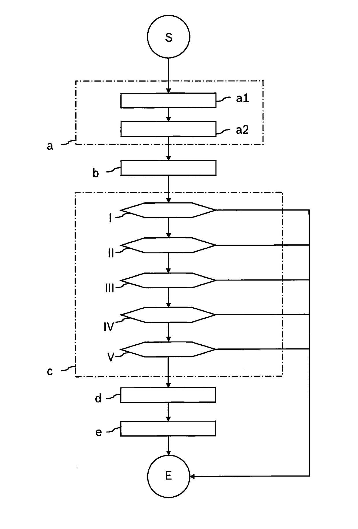
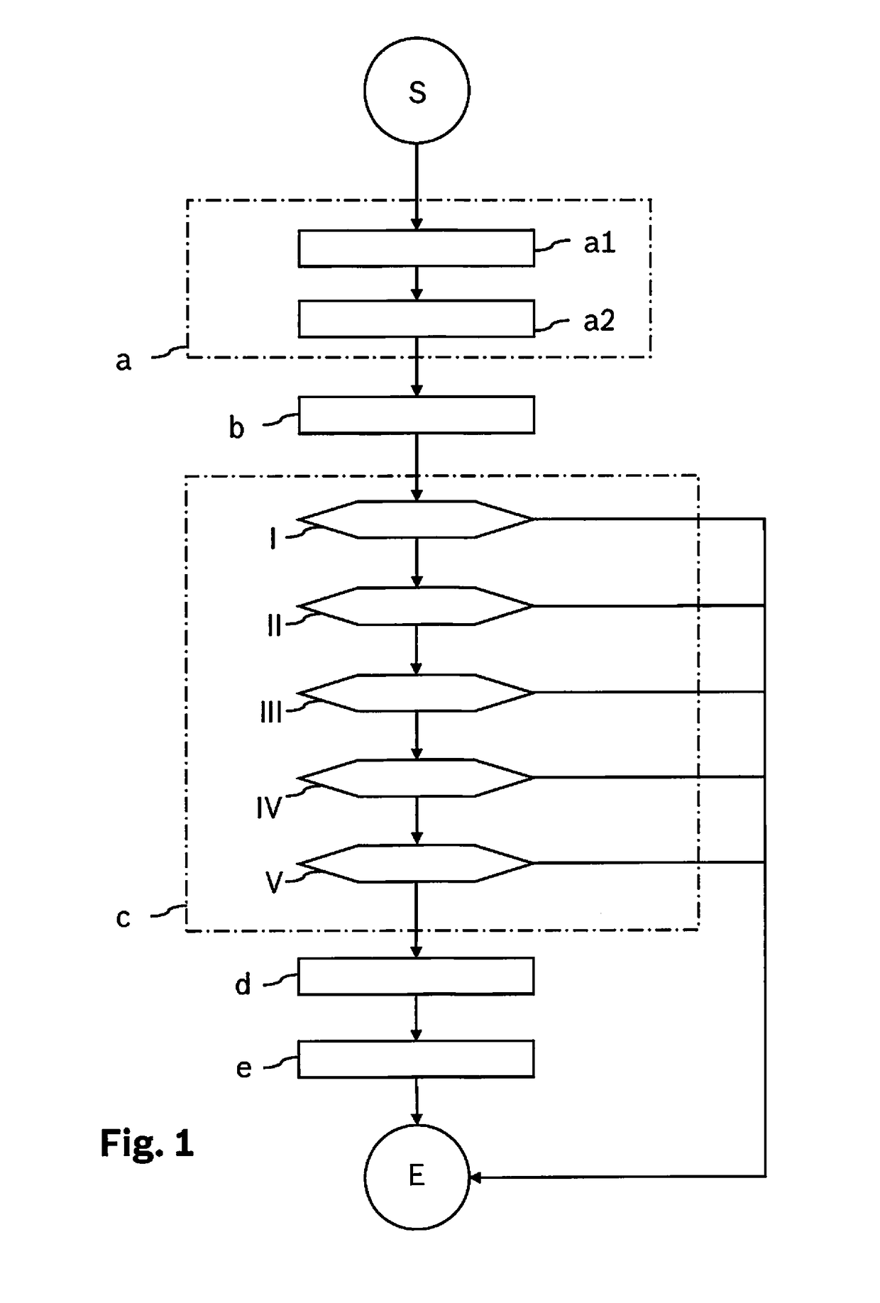
[0023]FIG. 1 shows a first exemplary embodiment of a method for ascertaining the internal resistance of an electrical energy accumulator according to the present invention. The method starts in start S. To begin with, an analog voltage signal Uanalog and an analog current signal Ianalog of the electrical energy accumulator are converted into digital voltage values U and digital current values I in a method step a. This analog to digital conversion takes place in method step a by a first partial step a1 and a second partial step a2. In first partial step a1, analog voltage signal Uanalog and analog current signal Ianalog are low-pass filtered, which is done with the aid of an analog low-pass filter, for example. In a second partial step a2, low-pass filtered analog voltage signal Uanalog and low-pass filtered analog current signal Ianalog are then sampled in order to obtain digital voltage values U and digital current values I. The sampling for analog voltage signal Uanalog and analo...


PUM


Abstract

A method is described for ascertaining an internal resistance of an electrical energy accumulator. For this purpose, an analog voltage signal and an analog current signal are subjected to an analog to digital conversion and subsequently to band-pass filtering in order to obtain filtered voltage values and filtered current values. These are then checked with regard to different calculation prerequisites, whereupon a zero-phase resistance is calculated. Then, the calculated zero-phase resistance is supplied as internal resistance

Description

BACKGROUND INFORMATION[0001]The internal resistance of an energy accumulator can be determined in different ways. In the automotive field, it is common to calculate the differential resistance, the zero-phase resistance or the Ohmic resistance and to determine the internal resistance therefrom. One method for ascertaining the differential resistance is described in the laid-open document WO 2006037694 A1.SUMMARY[0002]The present invention relates to a method for ascertaining an internal resistance of an electrical energy accumulator. According to the present invention, the internal resistance is determined by calculating a zero-phase resistance, which in turn is supplied as internal resistance to be ascertained. In so doing, the following method steps are carried out in sequential order:[0003]a. Analog to digital conversion of an analog voltage signal and an analog current signal of the electrical energy accumulator in order to obtain digital voltage values and digital current value...

Claims


Application Information

Patent Timeline
Patent Type & Authority Applications(United States)
IPC IPC(8): G01R31/36
CPCG01R31/3662G01R31/3648G01R31/3624G01R31/389G01R31/3842Y02E60/10H01M10/48
Inventor STOLCZENBERGER, ROBERTVARADI, FERENCBARANY, GABOR
Owner ROBERT BOSCH GMBH
Why Eureka
Try Eureka