Drilling rig apparatus and downhole tool assembly system and method

a drilling rig and tool assembly technology, applied in drilling machines and methods, fluid removal, construction, etc., can solve the problems of significant downtime, less robust ct technology, and less widespread adoption of ct technology in drilling, and achieve easy and time-efficient assembly

Active Publication Date: 2005-12-13
SAVANNA ENERGY SERVICES
View PDF27 Cites 83 Cited by
  • Summary
  • Abstract
  • Description
  • Claims
  • Application Information

AI Technical Summary

Benefits of technology

[0007]This invention provides an improved rig for drilling oil and gas wells. The rig includes components which permit both coiled tubing and jointed-pipe drilling with a minimum of ste...

Problems solved by technology

However, the adoption of CT technology in drilling has been less widespread than originally anticipated as a result of certain problems inherent in using CT in a drilling application.
For example, because CT tends to be less robust than jointed-pipe for surface-level drilling, it is often necessary to drill a pilot hole using jointed-pipe, cement casing into the pilot hole, and then switch over to CT drilling.
Additionally, when difficult formations such as boulders or gravel are encountered down-hole, it may be necessary to switch from CT drilling to jointed-pipe drilling until the formation is overcome, and then switch back to CT drilling to conti...

Method used


Image

  • Drilling rig apparatus and downhole tool assembly system and method
  • Drilling rig apparatus and downhole tool assembly system and method
  • Drilling rig apparatus and downhole tool assembly system and method

Examples


Embodiment Construction

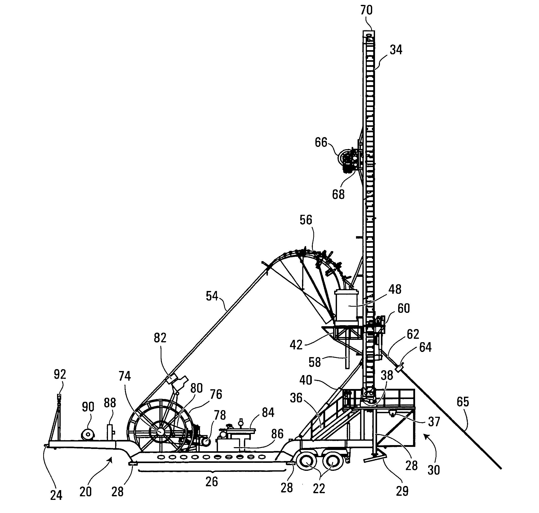
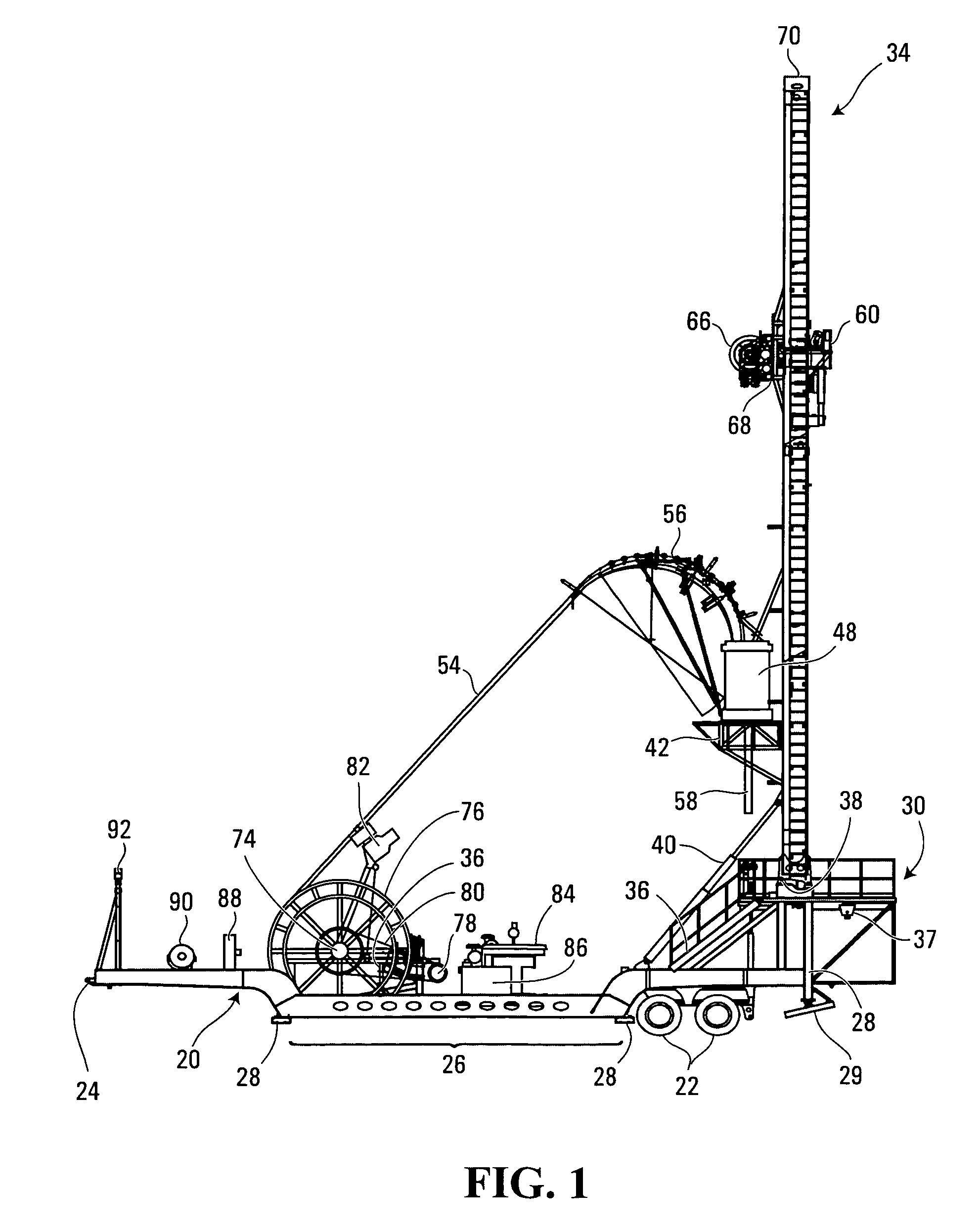
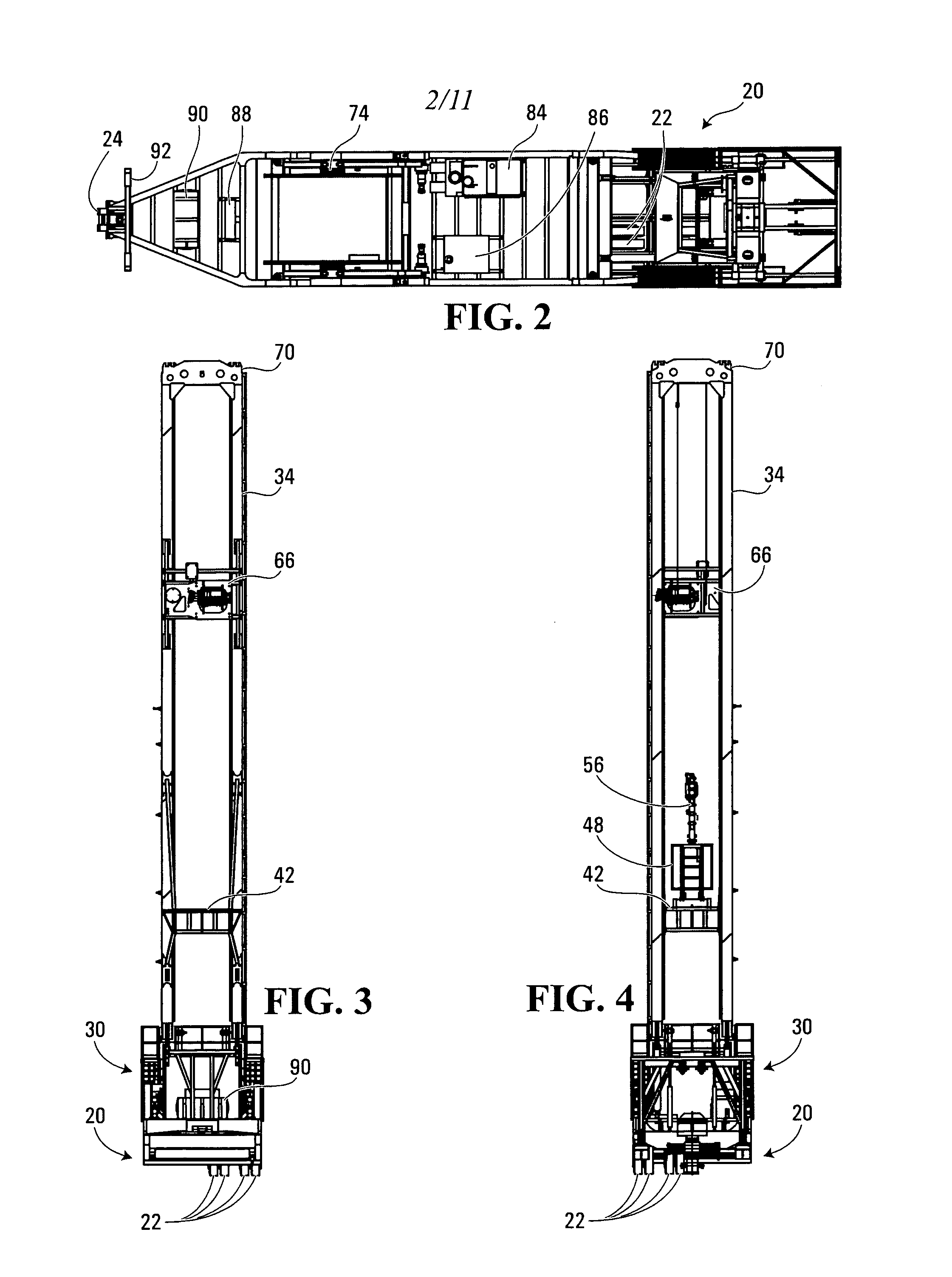
[0042]A preferred embodiment of the rig of the present invention is shown in the attached drawings. Its basic features are shown in FIG. 1.

[0043]In a broad sense, this rig includes a base, a mast, and drilling components.

[0044]In this preferred embodiment, the base is a wheeled carrier or trailer 20 which is adapted to be pulled by a motorized vehicle. The trailer 20 has wheels 22 located near its rear, and a hitch 24 located near its front for attachment to a motorized vehicle (not shown). The trailer 20 also has a lowered middle portion 26 so as to lower the center of gravity of the components placed on this portion of the trailer 20. While the wheeled carrier of the preferred embodiment rig has been described and illustrated as being one which is adapted to be pulled by a motorized vehicle, it is to be understood that the wheeled carrier may itself be self-propelled.

[0045]The trailer 20 has mounted thereon retractable outriggers or stabilizer legs 28 for stabilizing and levelling...


PUM


Abstract

A drilling rig is provided which is adapted to selectively drill using coiled tubing and jointed-pipe. The rig includes a base, a mast, a top drive slidably mounted to said mast for performing jointed-pipe operations, and a tubing injector for performing coiled tubing operations, mounted on said mast for selective movement from a first position in which the injector is in line with the mast and a second position in which the injector is out of line with the mast to permit jointed-pipe operations by the top drive. The rig is uniquely suited to easily and quickly assemble bottom hole assemblies (BHA's), and to connect such BHA's to coiled tubing.

Description

CROSS-REFERENCE TO RELATED APPLICATIONS[0001]This application claims the benefit of U.S. Provisional Application filed Apr. 15, 2003 under No. 60 / 462,738 which is incorporated herein in its entirety.FIELD OF THE INVENTION[0002]The invention relates to oil and gas drilling rigs, and in particular oil and gas drilling rigs used to drill using both coiled tubing and jointed-pipe.BACKGROUND OF THE INVENTION[0003]The use of coiled tubing (CT) technology in oil and gas drilling and servicing has become more and more common in the last few years. In CT technology, a continuous pipe wound on a spool is straightened and pushed down a well using a CT injector. CT technology can be used for both drilling and servicing.[0004]The advantages offered by the use of CT technology, including economy of time and cost are well-known. As compared with jointed-pipe technology wherein typically 30–45 foot straight sections of pipe are connected one section at a time while drilling the well bore, CT techno...

Claims


Application Information

Patent Timeline
IPC IPC(8): E21B7/02E21B15/00E21B19/22
CPCE21B15/00E21B19/22
Inventor CARRIERE, GENEGOLDADE, DON
Owner SAVANNA ENERGY SERVICES
Why Eureka
Try Eureka