Pulling grip with shroud

a grip and shroud technology, applied in the direction of cables, instruments, mechanical equipment, etc., can solve the problems of high tensile force of pulling tape and cable, weak link in system, and practice of covering it with a layer of tape, so as to facilitate the drawing of pulling grip

Inactive Publication Date: 2005-12-13
FEDERAL MOGUL WORLD WIDE
View PDF9 Cites 32 Cited by
  • Summary
  • Abstract
  • Description
  • Claims
  • Application Information

AI Technical Summary

Benefits of technology

[0017]A lubricious substrate, preferably a non-woven felt strip impregnated with a lubricant, may be interbraided with the filamentary members forming the shroud to provide lubricant facilitating the drawing of the pulling grip through the conduit.

Problems solved by technology

Because the lengths over which the cable is drawn may be long and tortuous, the pull tape and the cable may experience high tensile forces, largely due to the weight of the cable and the friction between the cable and the conduit.
While the cable and the pull tape individually are designed to take such forces, attachment of the tape to the cable proves to be the weak link in the system.
A disadvantage associated with the above-described kellem is the practice of covering it with a layer of tape, such as electrical tape.
The surfaces of the filamentary members making up the kellem gripping sleeve tend to be sharp and rough and, if uncovered, the gripping sleeve can act like a saw, damaging or severing items with the conduit or even the conduit itself during the draw.
The taping process is also very laborious in that it takes a lot of time to apply the tape before the pull as well as to remove the tape after the pull is completed.

Method used


Image

  • Pulling grip with shroud
  • Pulling grip with shroud
  • Pulling grip with shroud

Examples


Embodiment Construction

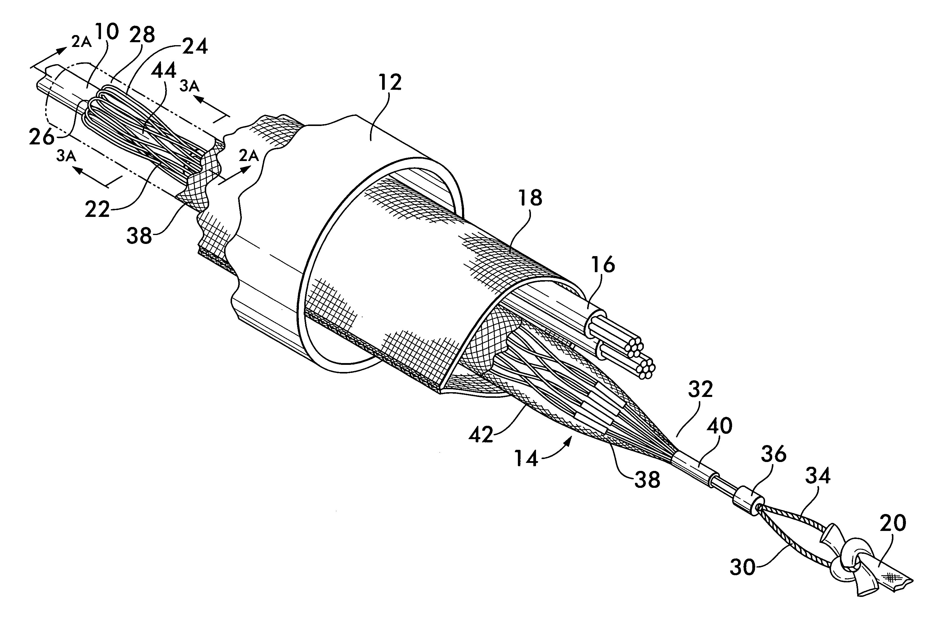
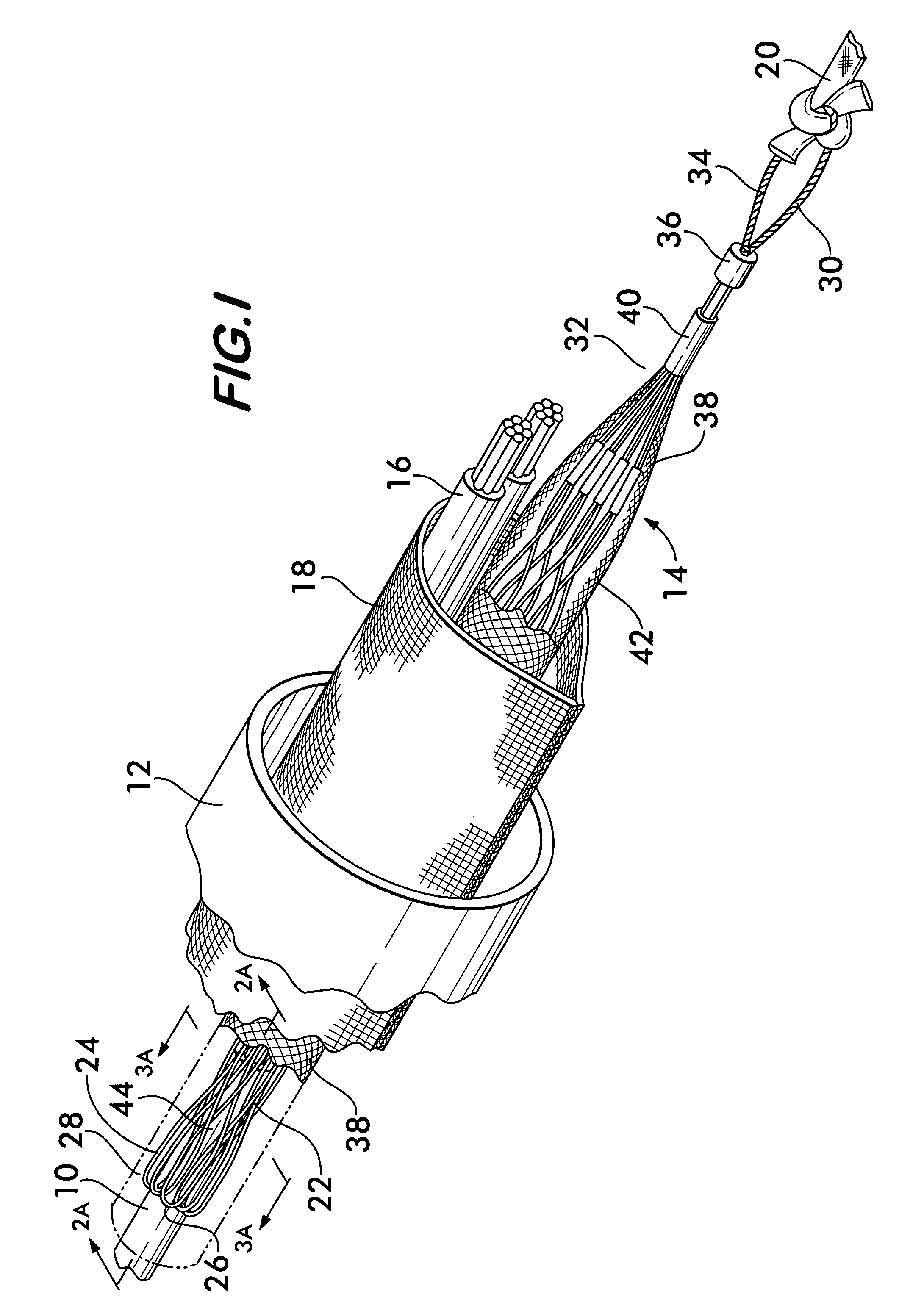
[0031]FIG. 1 shows a cable 10 being drawn through a conduit 12 using a pulling grip 14 according to the invention. Additional cables 16 are present within the conduit 12, preferably positioned within a protective sleeve 18 that is pre-positioned within the conduit with a pull tape 20.

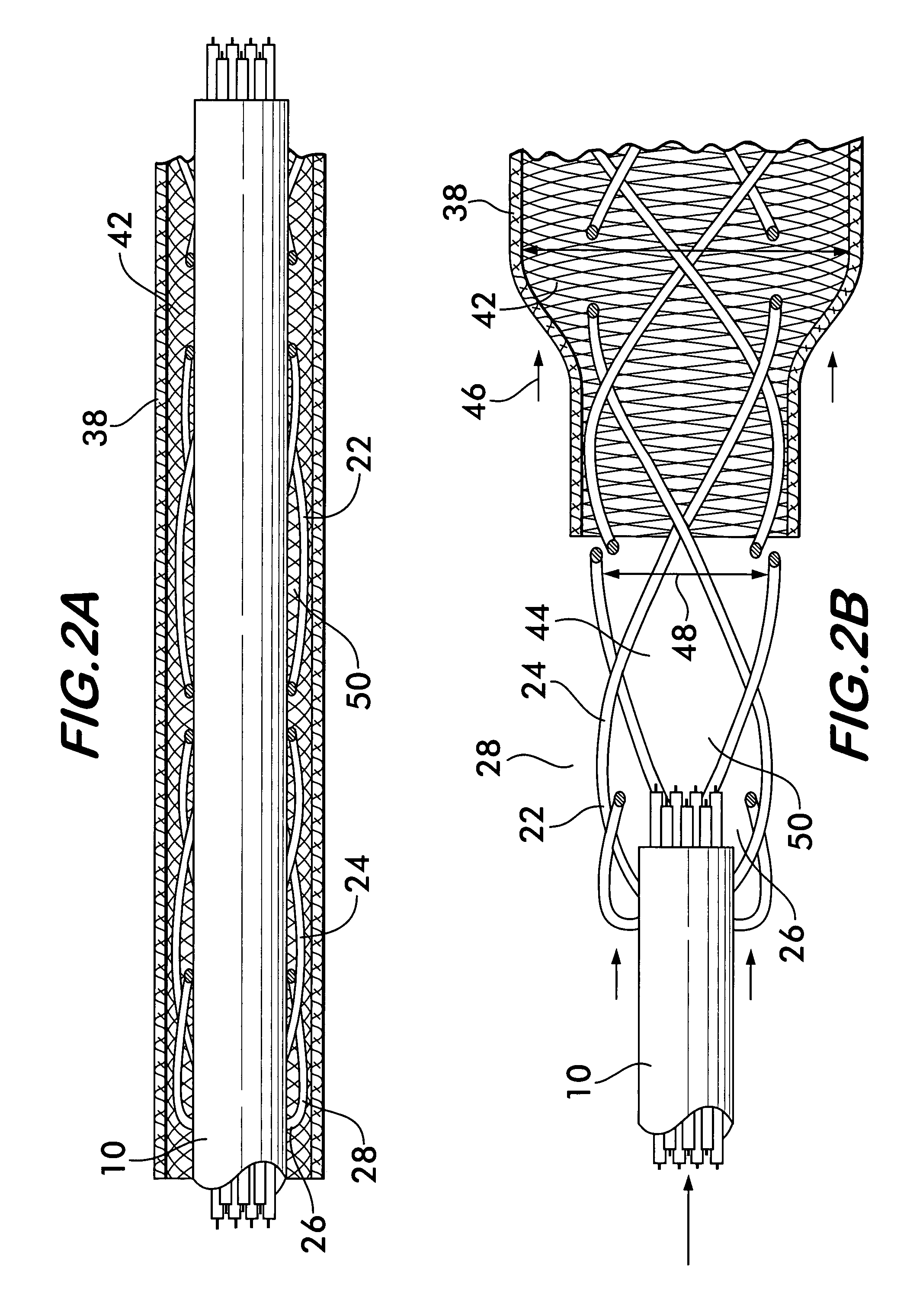
[0032]Pulling grip 14 comprises a flexible elongated gripping sleeve 22 formed of a plurality of filamentary members 24 braided together. Preferably, the filamentary members 24 are twisted steel cable for high strength and resiliency, the cable being preferably galvanized to inhibit corrosion. Other metals as well as non-metals are also feasible. Gripping sleeve 22 has an opening 26 at one end 28, the opening adapted to receive the cable 10 within the sleeve. An eye 30 is mounted on the gripping sleeve 22 at its opposite end 32. Eye 30 is preferably a loop 34 of twisted galvanized steel cable that is attached to the gripping sleeve using a swaged fitting 36. Pull tape 20 is tied to the loop 34 to draw t...


PUM


Abstract

A pulling grip for drawing a cable through a conduit is disclosed. The pulling grip includes a braided gripping sleeve that has an opening at one end which provides access to a central space surrounded by the sleeve. An eye for attachment to a pull tape is positioned at the opposite end of the gripping sleeve. The cable is received within the gripping sleeve, which is biased to engage and grip the cable along its length. Due to the trellis effect, the gripping sleeve grips the cable with greater force when under tension. One end of an elongated protective shroud is attached to the opposite end of the gripping sleeve. The other end of the shroud is free to move lengthwise along the sleeve toward and away from the attached end. The shroud prevents the gripping sleeve from contacting the conduit and its contents and thereby prevents the pulling grip from damaging these items during the pull.

Description

FIELD OF THE INVENTION[0001]The invention concerns devices such as kellems used to grip and pull elongated items such as electrical or fiber optic cables through ducts or conduits.BACKGROUND OF THE INVENTION[0002]Electrical and fiber optic cable is often laid within conduit for protection from the elements as well as from damage due to impact, cuts and abrasion. The conduits may be positioned underground and within buildings or other large structures and may extend over distances as long as a mile or more.[0003]Typically, the interior of the conduit is accessible only at isolated end points. Therefore, to lay cable within a conduit, a lightweight pull tape is first blown though the conduit using compressed air or other known techniques. The pull tape extends from one end of the conduit to the other end. One end of the pull tape is then attached to the cable, and the pull tape is drawn out of the conduit from its other end, thereby drawing the cable through the conduit from one end t...

Claims


Application Information

Patent Timeline
Patent Type & Authority Patents(United States)
IPC IPC(8): F16L3/01F16L55/165F16L55/18H02G1/08
CPCF16L55/1652F16L55/18G02B6/4465H02G1/081Y10T24/3998G02B6/545
Inventor UPTON, KENNETH C.
Owner FEDERAL MOGUL WORLD WIDE
Why Eureka
Try Eureka