
Needle assembly

a technology of needles and needles, applied in the field of needles, can solve the problems of increased discomfort and trauma for patients, inconvenient assembly of needles,

Inactive Publication Date: 2005-12-13
BECTON DICKINSON & CO
View PDF10 Cites 29 Cited by
  • Summary
  • Abstract
  • Description
  • Claims
  • Application Information

AI Technical Summary

Benefits of technology

[0024]Additionally, the blood collection needle assembly of the subject invention enables automatic shielding to occur without complex telescoping or pivoting shields and immediately upon withdrawal of the distal needle from the patient. Hence, a very high degree of safety can be achieved without complex mechanisms that could impede normal usage of the assembly.

Problems solved by technology

Unfortunately this initial observable flow of blood may not appear until several seconds after the venipuncture attempt.
Thus, a phlebotomist may withdraw the needle cannula and conduct the venipuncture procedure again, thereby causing additional discomfort and trauma for the patient.
However, the flashback chamber substantially complicates the prior art blood collection needle assembly and typically will increase both the cost and the size of the prior art blood collection needle assembly.
An accidental stick with a used needle cannula can be very painful and can transmit disease.
Hence, these prior art shields can impede the view of the collected blood that is required to assure a successful venipuncture.
Other prior art shields are sufficiently cumbersome that the phlebotomist may defer employing the shield, thereby creating a significant risk for an accidental needle stick.

Method used


Image

  • Needle assembly
  • Needle assembly
  • Needle assembly

Examples


Embodiment Construction

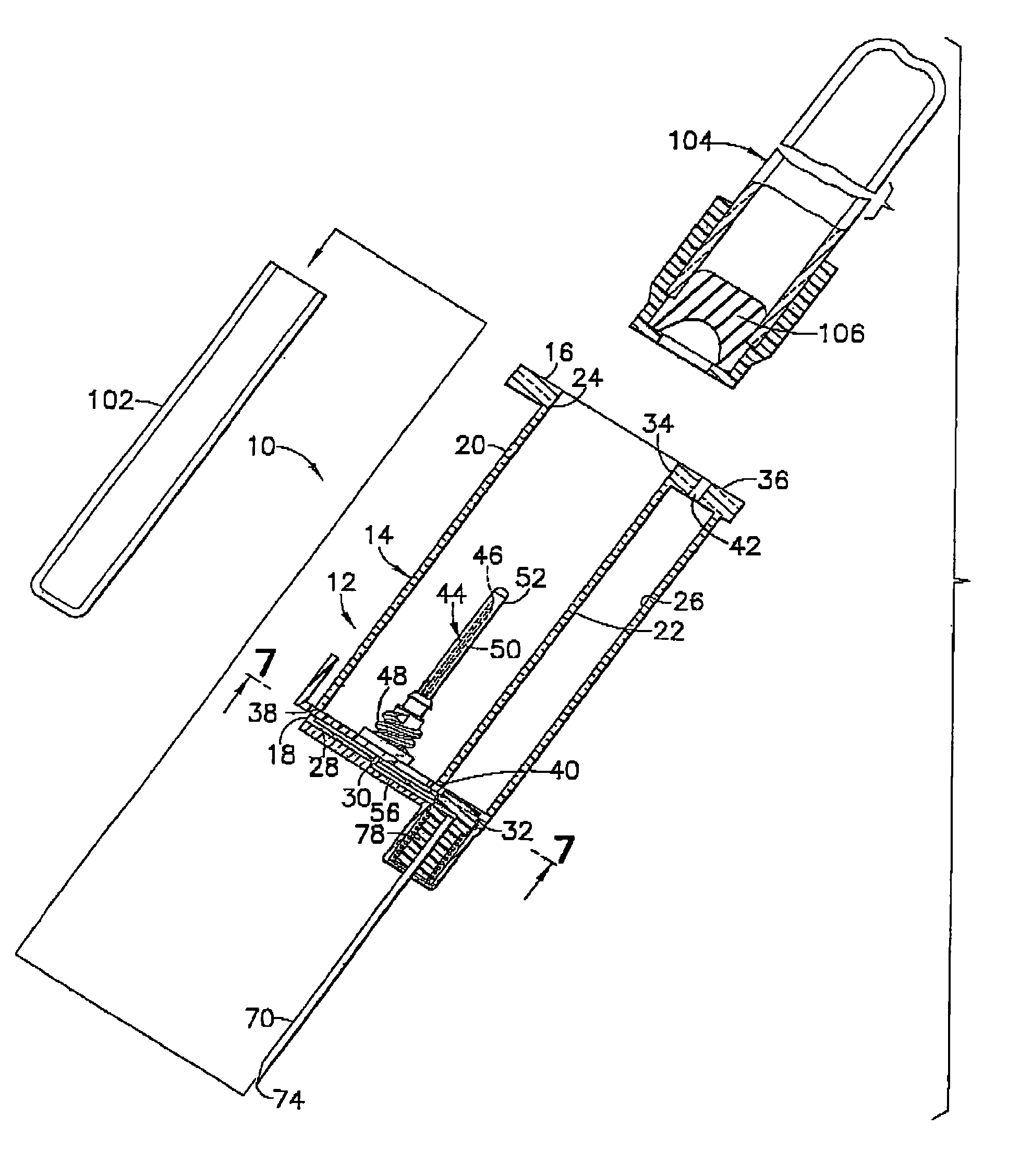
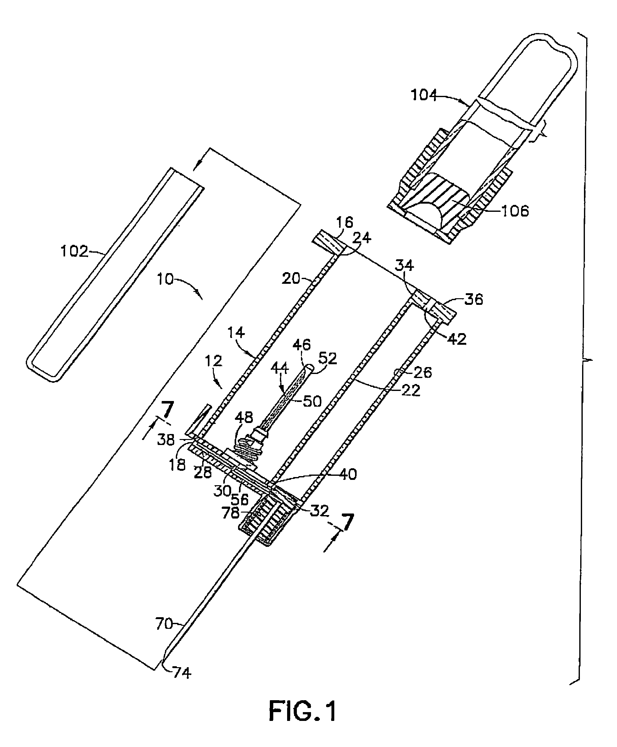
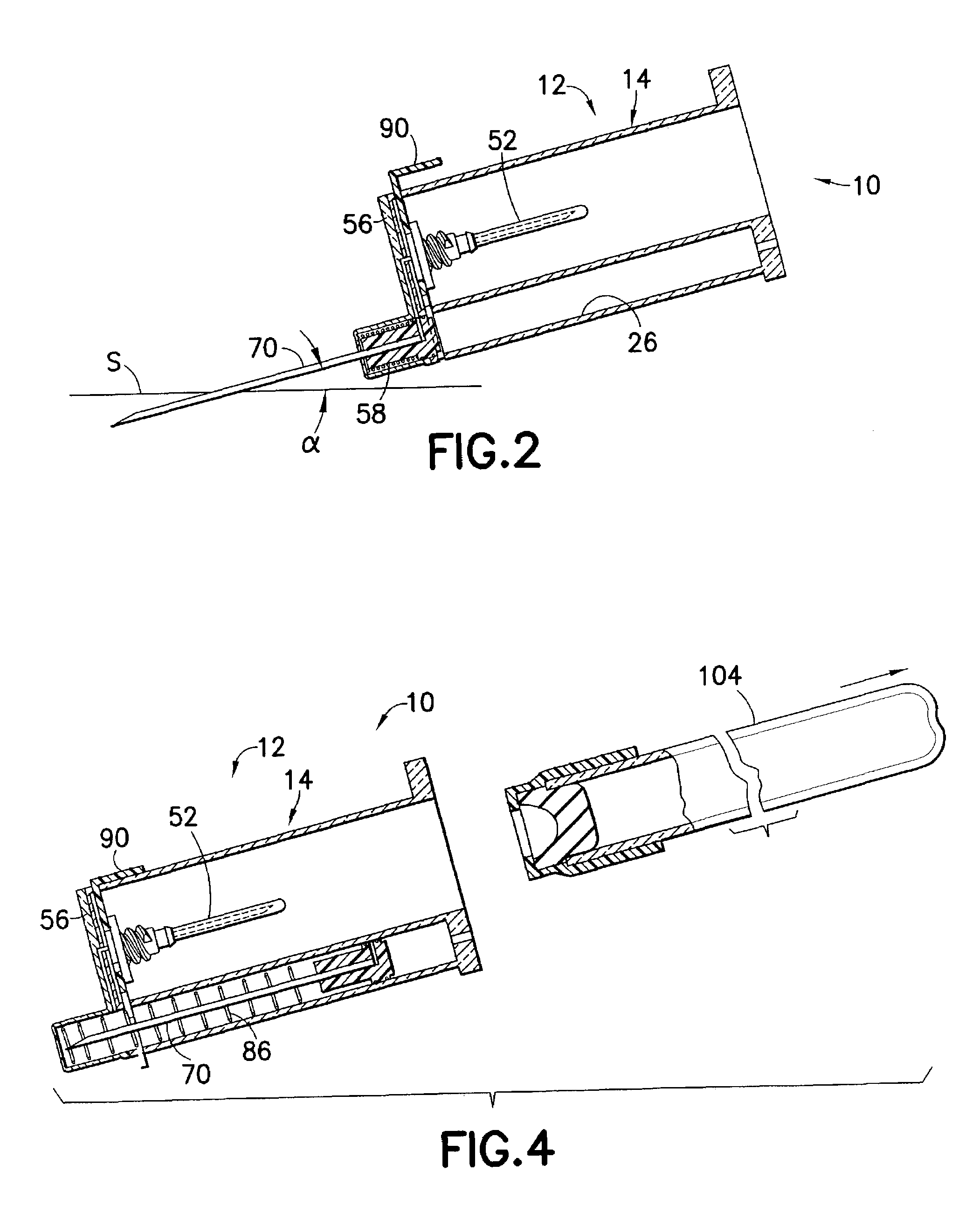
[0035]A blood collection needle assembly in accordance with the invention is identified generally by the numeral 10 in FIGS. 1–4. Blood collection needle assembly 10 includes a holder assembly 12 for holding needles and an evacuated blood collection tube. Holder assembly 12 includes a body 14 with a proximal end 16, an opposed distal end 18 and a tubular outer wall 20 extending between proximal end 16 and distal end 18. Holder body 14 further includes a transverse inner wall 22 extending substantially from proximal end 16 to distal end 18 and connecting spaced apart regions on tubular outer wall 20. Outer wall 20 and inner wall 22 cooperate to define a cylindrical tube receiving chamber 24 and a cylindrical needle receiving chamber 26 in bolder body 14.

[0036]Holder body 14 is characterized further by a distal wall 28 extending across distal end 18 of holder body 14. Distal wall 28 is characterized by aperture 30 substantially centrally aligned with tube receiving chamber 24 and an o...


PUM


Abstract

A blood collection needle assembly includes a holder body having a tube receiving chamber and a needle receiving chamber. A proximal needle is mounted to the holder body and projects into the tube receiving chamber. A distal needle is slidably mounted in alignment with the needle receiving chamber. A spring is provided to urge distal needle into the needle receiving chamber, and a trigger is provided for selectively permitting or preventing proximal movement of the distal needle. A transverse passage between the two needles is formed from a transparent material and provides indication of venus axis. The blood collection needle assembly is used to collect a sample of blood in a conventional manner. After collection of the blood, the trigger is actuated to release the distal needle and the spring propels the distal needle in a proximal direction for safe shielding within the needle receiving chamber of the holder body.

Description

RELATED APPLICATIONS[0001]This application claims priority on U.S. Provisional Patent Appl. No. 60 / 363,362 filed Mar. 11, 2002.BACKGROUND OF THE INVENTION[0002]1. Field of the Invention[0003]The subject invention relates to a needle assembly for collecting samples of fluid from a patient. The needle assembly includes a needle holder and a needle cannula that can be retracted into the holder after use.[0004]2. Description of the Related Art[0005]A needle assembly is used to acquire a sample of blood from a patient and to deposit the blood sample in an evacuated tube. The tube then is shipped from the site of collection to a laboratory for analysis.[0006]The typical prior art needle assembly includes a needle holder that has opposed proximal and distal ends and a tubular side wall extending between the ends. The proximal end of the needle holder is widely open. However, a wall extends partially across the distal end of the tubular side wall. A needle cannula is mounted to the distal e...

Claims


Application Information

Patent Timeline
IPC IPC(8): A61B5/15A61M5/32
CPCA61B5/1444A61M5/3232A61M2005/3227A61B5/15003A61B5/150389A61B5/150473A61B5/150526A61B5/150732A61B5/1545A61B5/150656
Inventor ZURCHER, ROBERT
Owner BECTON DICKINSON & CO
Learn More