Dimming-control lighting apparatus for incandescent electric lamp

a technology of incandescent electric lamps and lighting apparatuses, which is applied in the direction of electric variable regulation, process and machine control, instruments, etc., can solve the problems of inability to adjust the color temperature, adversely affect the image quality, and affect the effect of lighting direction, so as to achieve less color temperature change

Inactive Publication Date: 2005-12-13
NIPPON HOSO KYOKAI +1
View PDF8 Cites 46 Cited by
  • Summary
  • Abstract
  • Description
  • Claims
  • Application Information

AI Technical Summary

Benefits of technology

[0018]The present invention has been achieved in view of the above problems. It is therefore an object of the present invention to provide a dimming-control apparatus for an incandescent electric lamp, using the dimming power source that has already been installed in various studios or theaters, which apparatus effects less change of color temperature.

Problems solved by technology

However, when the dimming of an incandescent electric lamp is adjusted, color temperature, as well as the flux of light, occurring in the incandescent electric lamp is changed, which results in a degraded directing effect in lighting.
In particular, in a TV studio when using a TV camera or a photo studio when photographing in color, the change of color temperature due to an adjustment of dimming adversely affects image quality.
As mentioned above, measures including using color filters or adjusting the light device or selecting the arrangement position of the same so as to avoid the decrease of color temperature have been adopted; however, these measures are complicated and troublesome, and cannot be regarded as complete methods for correcting the change of color temperature.
However, this lighting apparatus generally uses an AC power source, and requires control signal lines from the controller for controlling the dimmer.
Thus, in order to use the above-mentioned dimming-control lighting apparatus for an incandescent electric lamp, new lines for a general AC power source and for control signals should be installed, which results in difficulty when employing incandescent in studios or theaters in which the lighting apparatus has already been installed.

Method used


Image

  • Dimming-control lighting apparatus for incandescent electric lamp
  • Dimming-control lighting apparatus for incandescent electric lamp
  • Dimming-control lighting apparatus for incandescent electric lamp

Examples


Embodiment Construction

[0047]Hereinafter, embodiments of the present invention will be described with reference to the accompanying drawings.

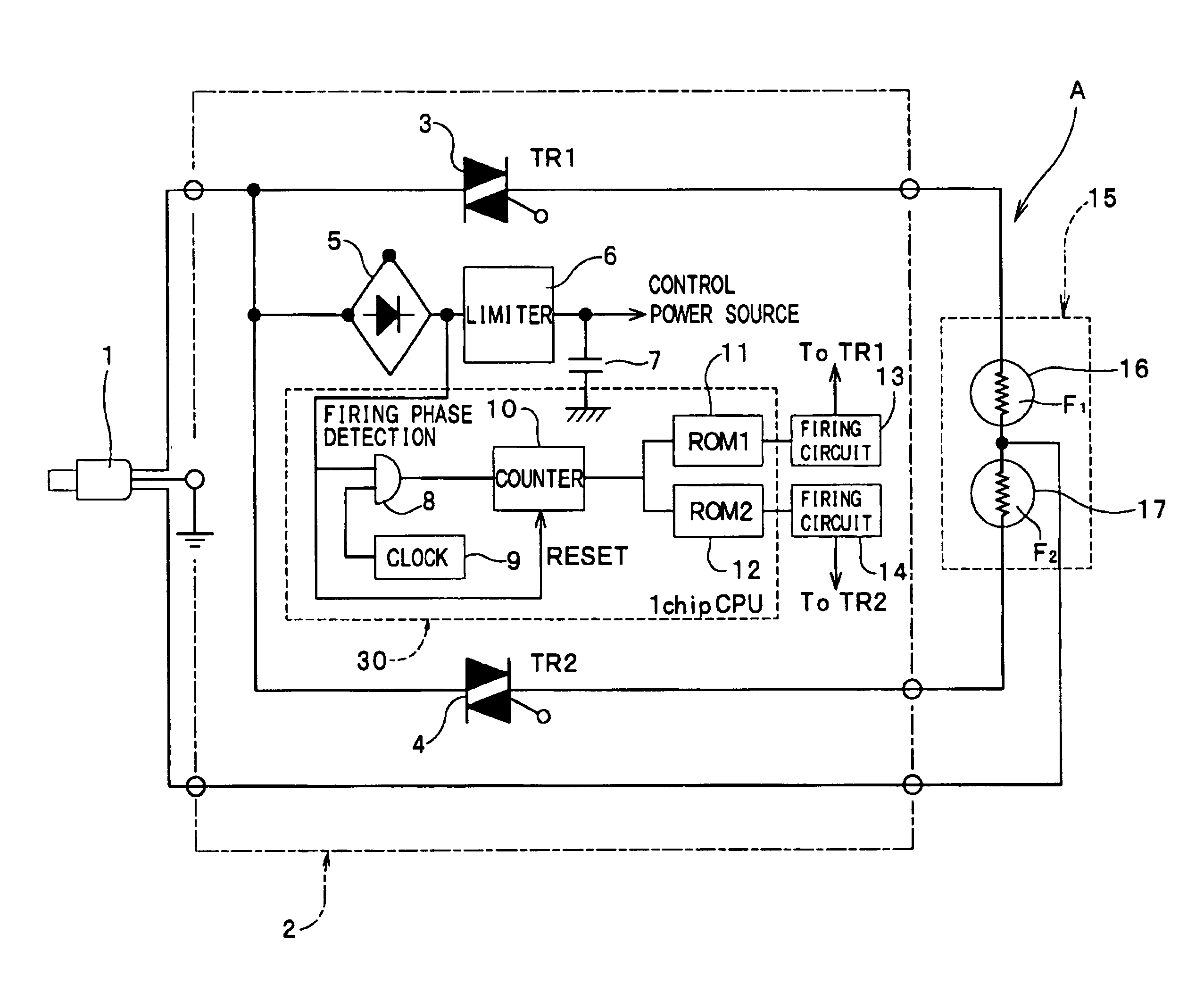
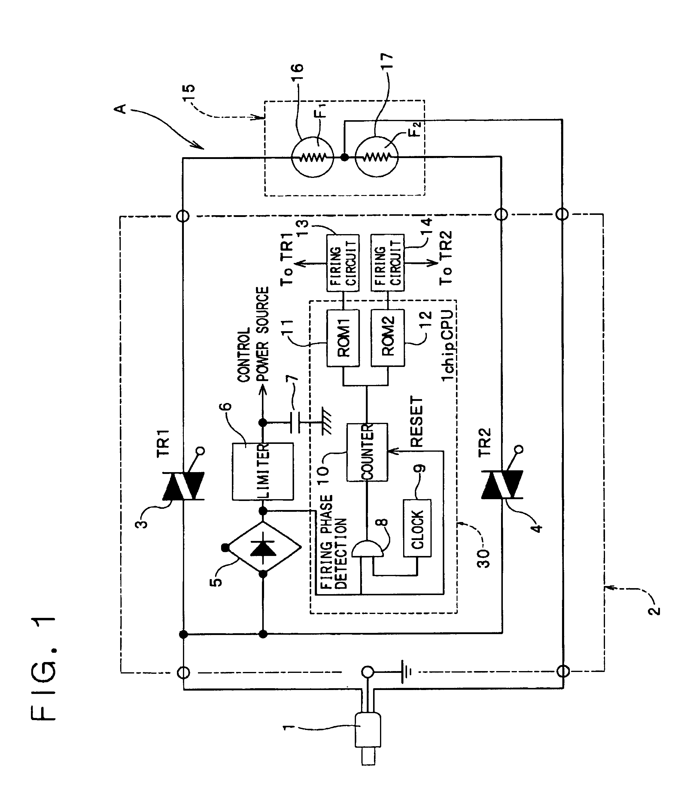
[0048]FIG. 1 is a circuit diagram of a dimming-control lighting apparatus A for an incandescent electric lamp. Reference numeral 1 indicates a tripole connector having an earth line and a power source for connecting the present lighting apparatus to a dimming power source (not shown), reference numeral 15 indicates a lighting device, reference numeral 2 indicates a control box for dimming the lighting device 15 based on a sawtooth voltage supplied from the dimming power source to the present lighting apparatus A, and the lighting device 15 includes a first lamp 16 with a first encapsulated filament F1 and a second lamp 17 with a second encapsulated filament F2.

[0049]The control box 2 includes a thyristor (TR1) 3 as a first power control unit connected to the first filament F1, a thyristor (TR2) 4 as a second power control unit connected to the second filament F2, ign...


PUM


Abstract

A dimming-control lighting apparatus for an incandescent electric lamp with less accompanying color temperature change, using a dimming power source installed in TV studios or theater stages, is disclosed. The voltage of the first filament whose rated voltage is lower than the maximum output voltage of a dimming power source rapidly rises to the sawtooth voltage of the dimming power source, and after the first filament reaches a constant color temperature, the output of the second filament having the same rated voltage as the maximum output voltage of the dimming power source is delayed to thereby light the second filament. Thyristors and connected to the first filament and the second filament, respectively, are operated by the control of control means based on the detection of the ignition phase angle of the sawtooth wave of the dimming power source to thereby light the first filament and the second filament (lamps), as mentioned above, so that dimming control having a smaller color temperature change is performed using the dimming power source.

Description

BACKGROUND OF THE INVENTION[0001]1. Field of the Invention[0002]The present invention relates to a dimming-control lighting apparatus for an incandescent electric lamp used in directing spaces such as a TV studio, a theater stage, or a photo studio, which uses a lighting device employing the incandescent electric lamp as a light source.[0003]2. Description of the Related Art[0004]In the related art, it is indispensable to freely control the flux of light of the lighting device in the directing spaces such as the TV studio or theater stage; as such, incandescent electric lamps have been widely used as the light sources of the lighting devices.[0005]However, when the dimming of an incandescent electric lamp is adjusted, color temperature, as well as the flux of light, occurring in the incandescent electric lamp is changed, which results in a degraded directing effect in lighting.[0006]In particular, in a TV studio when using a TV camera or a photo studio when photographing in color, t...

Claims


Application Information

Patent Timeline
Patent Type & Authority Patents(United States)
IPC IPC(8): H05B37/02G05F1/00H01K1/62H05B39/04
CPCH05B39/044Y02B20/146Y10S323/905Y02B20/00
Inventor YANAI, NAOKIKIMURA, SABUROKITA, HIROSHIYAMAZUKA, HIDEMITSU
Owner NIPPON HOSO KYOKAI
Why Eureka
Try Eureka