Method for communication between central terminal and multiple transponders

a communication method and transponder technology, applied in pulse position modulation, pulse technique, instruments, etc., can solve the problems of data collisions with multiple transponders, large amount of information that must be communicated through such systems, and large distances for conventional systems providing such communications

Inactive Publication Date: 2005-12-13
INTPROP LLC
View PDF17 Cites 54 Cited by
  • Summary
  • Abstract
  • Description
  • Claims
  • Application Information

AI Technical Summary

Benefits of technology

[0007]The present inventor has discovered a new communication method in which multiple transponders transmit information to a central monitoring terminal in the form of a pulsed packets or bursts of a sub-carrier. Bursts at two distinct subcarrier frequencies are respectively transmitted, where one subcarrier frequency signifies a data change from a low level to a high level (e.g., zero to one) in the data s

Problems solved by technology

Often the amount of information that must be communicated by way of such systems is fairly limited.
Nevertheless, conventional systems for providing such communications require significant amounts of energy to be transmitted over long distances.
Also, data collisions with multiple transponders can occur with only a few transponders present.
Classical methods also require either significant bandwidth or very long read times when many t

Method used


Image

  • Method for communication between central terminal and multiple transponders
  • Method for communication between central terminal and multiple transponders
  • Method for communication between central terminal and multiple transponders

Examples


Embodiment Construction

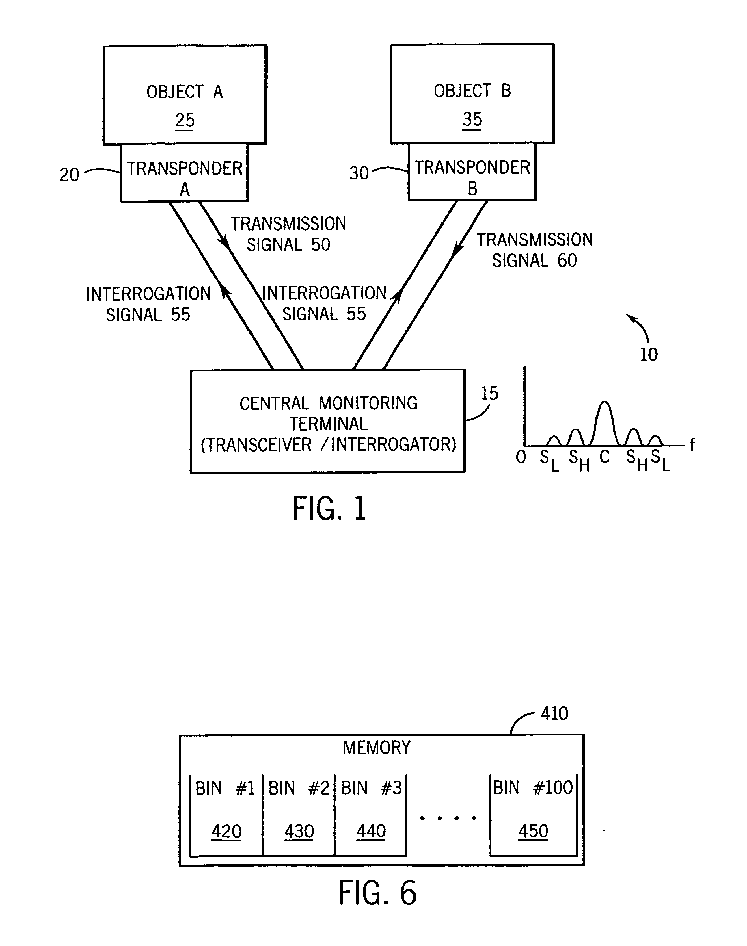
[0020]Referring to FIG. 1, an exemplary wireless communication system 10 employs one or more transponders or “tags” that are in communication with a central monitoring terminal 15. In the embodiment shown, first and second transponders 20 and 30, respectively, are in communication with the central monitoring terminal 15, although in alternate embodiments only one, or more than two, transponders are in communication with the central monitoring terminal. As discussed below, the present invention is particularly suited for allowing communication between a large number of (e.g., one thousand or more) transponders and the central monitoring terminal 15.

[0021]Further as shown in FIG. 1, in the present embodiment, the first and second transponders 20,30 are attached to first and second objects 25 and 35, respectively. The objects 25,35 can be any objects for which the presence or operational status may be of interest. For example, the objects 25,35 can be machine components located in a fa...


PUM


Abstract

A method of communicating information from first and second transponders (or multiple transponders) to a central monitoring device, and a communications apparatus, are disclosed. The method includes receiving a starting indication at the transponders, determining start times for the transponders in response to that indication, and transmitting first and second sets of bursts from the first and second transponders, respectively. The bursts of the first set occur at at least some of a first set of potential transmission times within an interrogation period, and the bursts of the second set occur at at least some of a second set of potential transmission times during that period. Each of the potential transmission times of the burst sets are respectively determined in relation to the start times of the respective transponders. The potential transmission times of the respective burst sets are separated from one another by one of a bit-cell period and a multiple thereof.

Description

FIELD OF THE INVENTION[0001]The present invention relates to wireless communication systems and, more particularly, relates to a wireless communication system in which a central monitoring terminal is in communication with multiple monitored devices.BACKGROUND OF THE INVENTION[0002]In many situations, it is desirable to identify and monitor the status of multiple objects that are in proximity with one another. For example, in a commercial or industrial facility such as a factory or a warehouse, multiple sensors, motors, or other devices can be positioned at different locations around the facility. In such an environment, it can be desirable to monitor which of these devices are present and, if desired, which devices are operating properly, as well as to receive and transmit information from and to these devices. Similarly, in a hospital environment, it can be desirable to monitor and communicate information with numerous devices such as patient monitors, analytical devices, food car...

Claims


Application Information

Patent Timeline
IPC IPC(8): G06K7/00
CPCG06K7/0008G06K7/10039
Inventor REINING, WILLIAM N.
Owner INTPROP LLC
Why Eureka
Try Eureka