Depth-of-field effects using texture lookup

Active Publication Date: 2005-12-13
NVIDIA CORP
View PDF4 Cites 33 Cited by
  • Summary
  • Abstract
  • Description
  • Claims
  • Application Information

AI Technical Summary

Benefits of technology

[0012]For some embodiments, a filtering function may be applied to filter depth values of the depth texture map. For some embodiments, one or more actions which may be included are: creating a set of texture coordinate tuples, generating a color value for each texture coordinate tuple by interpolation using color values from at least one of the mip-map layers chosen according to the mip-map layer selection value, and generating a color value for the pixel by blending together the color values generated for each texture coordinate tuple.
[0013]One or more other aspects of the present invention include providing an application program interface (API) to interface with a graphics processor, receiving the 3D sce

Problems solved by technology

Generally, higher frame rates are possible with a lower number of pixels, but visually perceptible image quality may suffer.
For example, an image on a 2D screen with a high pixel density may still appear unrealistic if all the objects appearing in the scene are in focus.
The unrealistic appearance is due to an incorrect (or lack of) dept

Method used


Image

  • Depth-of-field effects using texture lookup
  • Depth-of-field effects using texture lookup
  • Depth-of-field effects using texture lookup

Examples


Embodiment Construction

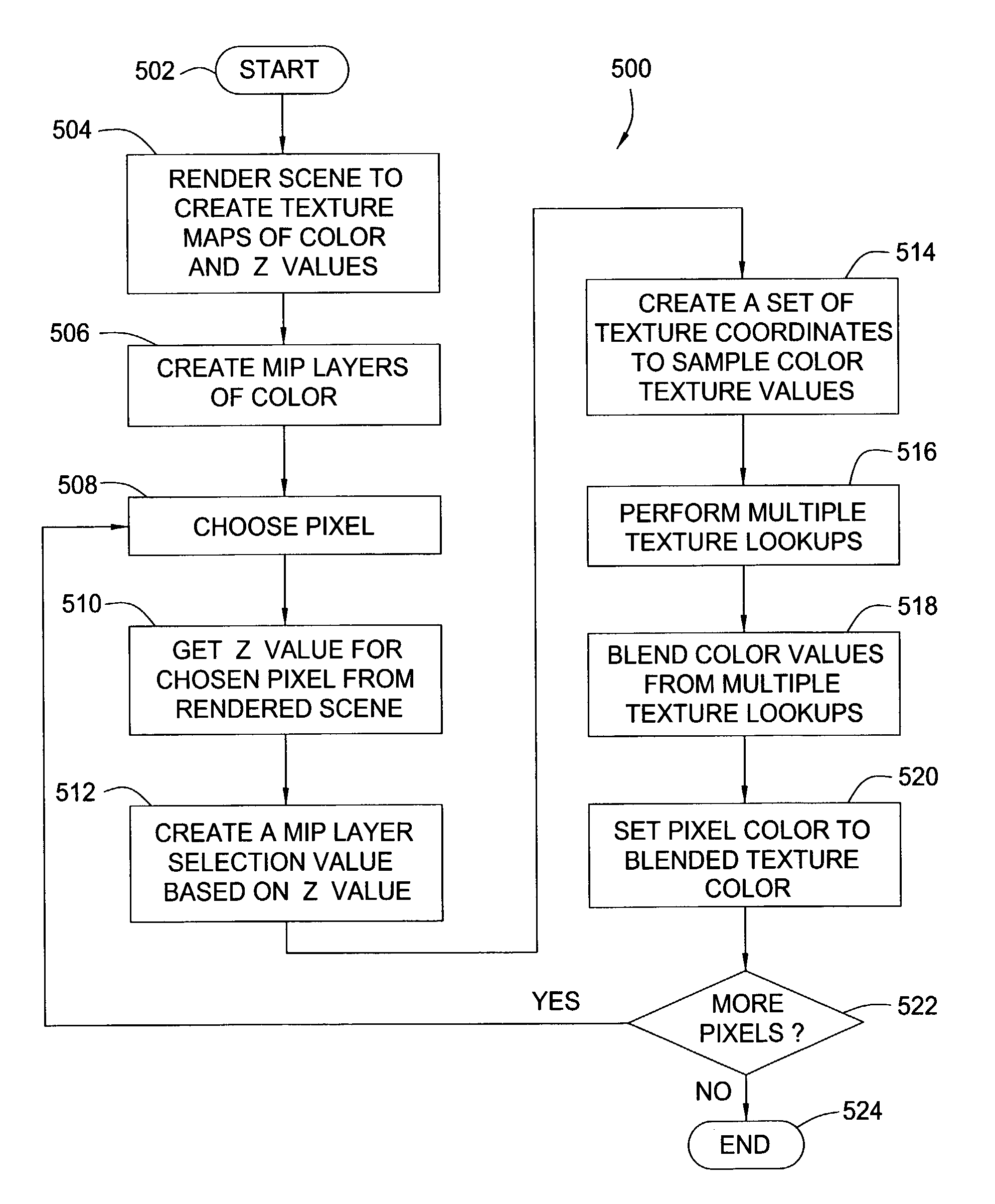
[0028]The present invention generally provides for performing depth-of-field corrections when rendering a three-dimensional (3D) scene on a two-dimensional (2D) screen of pixels. Included are capturing depth and color values for each pixel as textures in a first pass of rendering the 3D scene, and subsequently blurring out-of-focus portions of the scene based on captured depth values for the pixels in a second pass of rendering the object. For different embodiments, different operations may be performed in either hardware or software or a combination thereof.

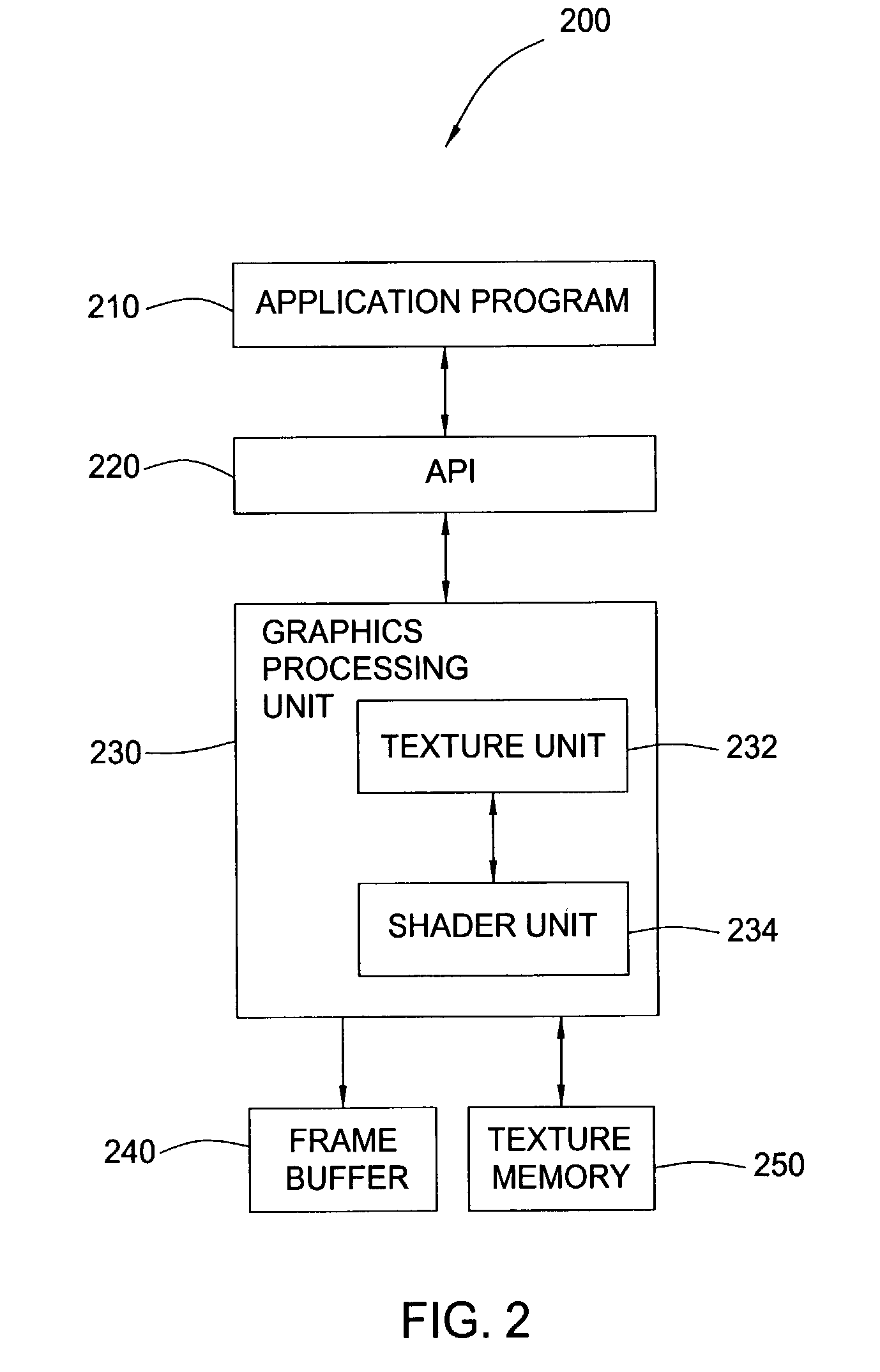
[0029]FIG. 2 illustrates a schematic block diagram of a graphics system 200 that may be used to practice one or more aspects of the present invention. The graphics system 200 generally includes an application program 210, application program interface 220, a graphics processing unit (GPU) 230, and a frame buffer 240. The application program 210 may generate a graphic image to be displayed on a display. The API 220 serves as an i...


PUM


Abstract

A graphical processing unit (GPU) and methods for rendering a three-dimensional (3D) scene generated in a field of view having in-focus and out-of-focus regions on a two-dimensional (2D) screen region of pixels are described. One method includes initially rendering the scene to create color and depth texture maps and creating mip-map layers for the color texture map. The method further comprises subsequently rendering the scene by, for each pixel: creating a mip-map layer selection value as a function of a depth of the pixel from the depth texture map, generating a color value by interpolation using color values from at least one of the mip-map layers chosen according to the mip-map layer selection value, and setting a color of the pixel to the generated color texture.

Description

BACKGROUND OF THE INVENTION[0001]1. Field of the Invention[0002]One or more aspects of the present invention generally relate to computer graphics and, more particularly, to rendering three-dimensional (3D) scenes with depth-of-field correction.[0003]2. Description of the Related Art[0004]In general, three-dimensional (3D) computer graphics is the art and science of generating 3D scenes on a two-dimensional (2D) computer screen. In a 3D animation, a sequence of images is displayed, giving the appearance of motion in three-dimensional space. Interactive 3D computer graphics allows a user to change viewpoint or geometry in real-time, thereby requiring the graphics system to create new images. Conventionally, the higher the number of images that are displayed per second, commonly referred to as the frame rate, the smoother the animation will appear but the more processing power and system bandwidth is required. For example, the human eye may detect new images coming onto the screen at ...

Claims


Application Information

Patent Timeline
IPC IPC(8): G06T15/20G06T15/40G09G5/00
CPCG06T15/04G06T15/405
Inventor BASTOS, RUI M.LEW, STEPHEN D.BEESON, CURTIS A.DEMERS, JR., JOSEPH E.
Owner NVIDIA CORP
Why Eureka
Try Eureka