Method of displaying magnified and reduced areas and apparatus thereof

a technology of magnified and reduced areas and displays, applied in the field of user interfaces, can solve the problems of difficult to recognize which portion of the whole diagram is magnified or reduced, and cannot accommodate the whole diagram on the display area,

Inactive Publication Date: 2005-12-13
IBM CORP
View PDF29 Cites 65 Cited by
  • Summary
  • Abstract
  • Description
  • Claims
  • Application Information

AI Technical Summary

Benefits of technology

[0005]According to the present invention, diagram configuration information including display specification information such as the color and the pattern of the display are changed to characterize the magnification or reduction ratio of portions of a screen display. The display specification information including information concerning the shade of color and / or the pattern density are changed to reflect the magnification or reduction ratio as a ratio of the portions of the diagram magnified or reduced. For example, the display specification information for a reduced area calls for use of a deep or intense color in order to indicate that the area is compressed and the intensity is varied in accordance with the areas reduction ratio. Diagram linkage information determines whether or not an increase in the size of a certain portion of the diagram affects the other portions such that the other portions must be reduced so that the whole diagram can be accommodated in a screen.

Problems solved by technology

However, with this method, the whole diagram cannot be accommodated on the display area.
When the magnified portion and the reduced portions are so mixed on a display screen, it has been extremely difficult to recognize which portion is magnified or reduced, and to which extent the portion is magnified or reduced.

Method used


Image

  • Method of displaying magnified and reduced areas and apparatus thereof
  • Method of displaying magnified and reduced areas and apparatus thereof
  • Method of displaying magnified and reduced areas and apparatus thereof

Examples


Embodiment Construction

[0018]Descriptions will be made for the present invention with reference to an embodiment of a record design as a part of a program development tool.

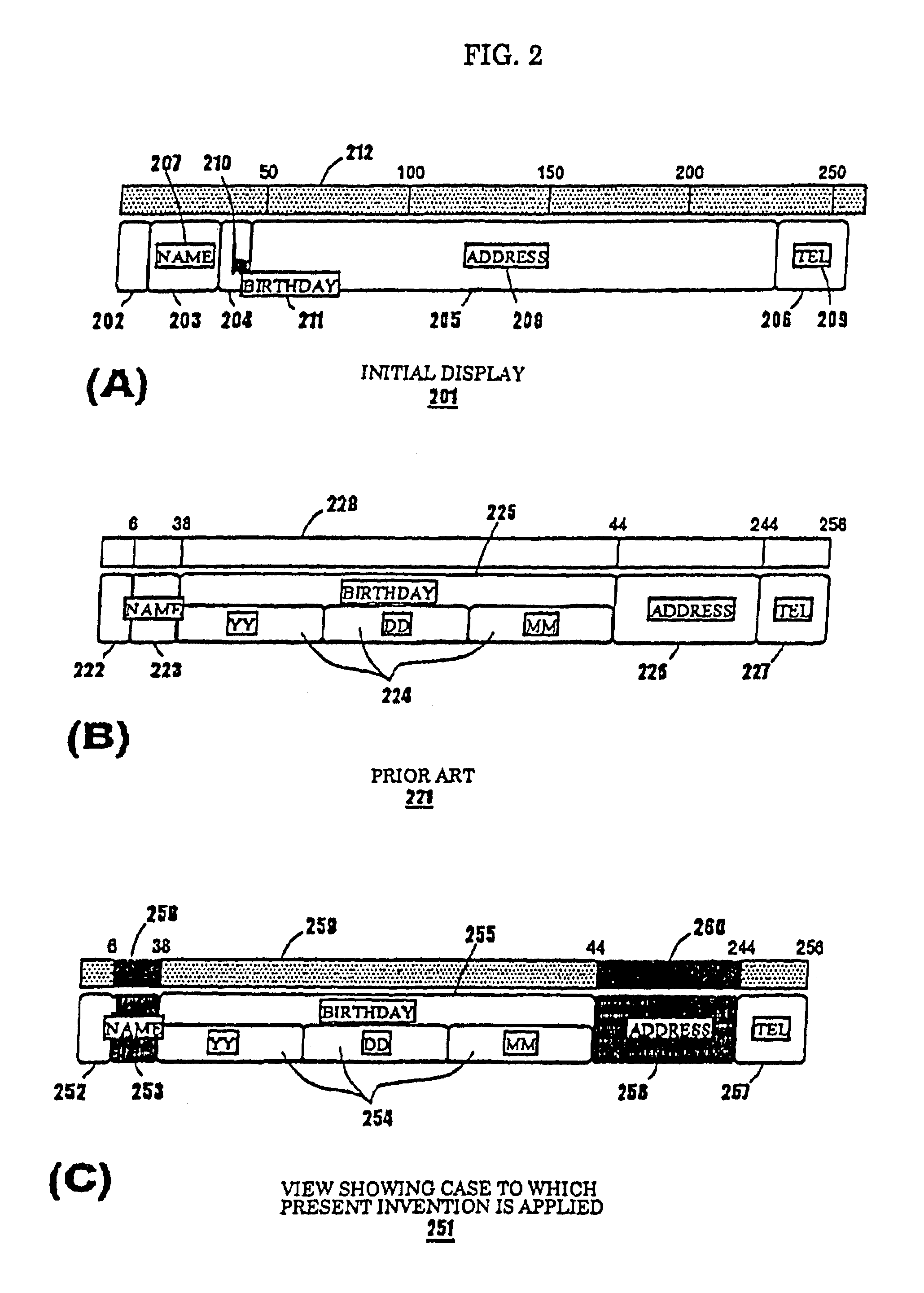
[0019]As shown in FIG. 2(A), record data contains variables such as “NAME”, “BIRTHDAY”, “ADDRESS” and “TEL”, which are used in an application program. These variables are referred to as “data items.

[0020]Reference numeral 201 denotes an initial display of one record. This record includes five data items 202 to 206. Data item names 207, 208 and 209 are displayed on the data items where there is sufficient display area. Where a display area has insufficient space, a data item name denoted by numeral 211 is displayed when a cursor 210 of a pointing device points to the display area. A scale 212 appears across the top of the record data. In FIG. 2(A), the data items are displayed so as to have the size corresponding respectively to lengths of the data items.

[0021]In FIG. 2(b), the whole of one record displayed on the screen with the data it...


PUM


Abstract

Magnified and/or reduced areas of a display are easily determined by the shades of color and a pattern densities which correspond to the magnification or reduction ratio of areas of the display. The areas that have been magnified and/or reduced are presented by varying color intensity within areas reduced in size displayed with a deep hue in color to indicate that the area is compressed and a magnified area is displayed with a lighter color to indicate its expansion. Moreover, images of the display can be presented with a specification corresponding to each magnification or reduction ratio by linking the display with a movement of a pointing device, thus realizing a very easy-to-operate user interface.

Description

FIELD OF THE INVENTION[0001]The present invention relates to a user interface capable of easily determining which area has been magnified / reduced and to which extent the area has been magnified / reduced at an editorial work for a diagram, a document or the like. More particularly, the present invention relates to a method capable of changing a display in accordance with magnifying / reducing operations by a user, and an apparatus thereof.BACKGROUND OF THE INVENTION[0002]Conventionally, when a portion of a diagram is desired to be magnified and displayed, it has been the practice of magnifying not only the objective area (portion) but also the whole diagram as shown in diagram 101 of FIG. 1. However, with this method, the whole diagram cannot be accommodated on the display area. Another conventional practice has been to magnify the portion of the diagram desired to be magnified, and of displaying it in the vicinity of an original diagram as shown in a diagram 102 of FIG. 1. With this pr...

Claims


Application Information

Patent Timeline
Patent Type & Authority Patents(United States)
IPC IPC(8): G06F3/048G06F3/033G06F3/0484G06T3/40G06T11/80G09G5/36
CPCG06F3/0481G06F2203/04805
Inventor WATANABE, TERUE
Owner IBM CORP
Why Eureka
Try Eureka