

Zoom lens, and electronic imaging system using the same
a technology of electronic imaging and zoom lens, which is applied in the field of zoom lens and electronic imaging system, can solve the problems of the thickness of the optical system, the bottleneck in reducing the depth dimension of the camera, etc., and achieve the reduction of swindle signals like moire fringes, the effect of high image-formation capability and reduced contrast of frequency components greater than the nyquist threshold
- Summary
- Abstract
- Description
- Claims
- Application Information
AI Technical Summary
Benefits of technology
Problems solved by technology
Method used
Image

Examples
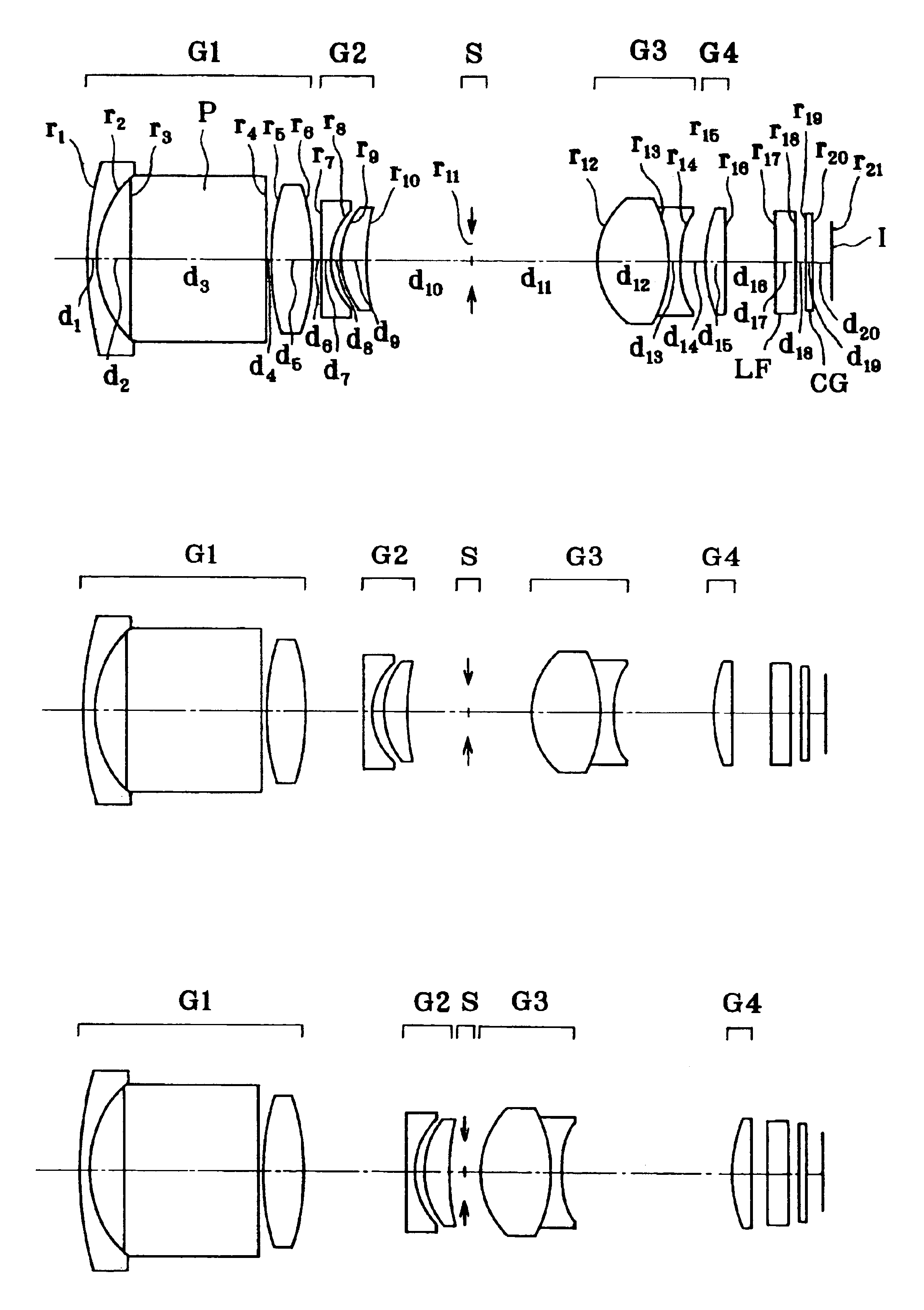
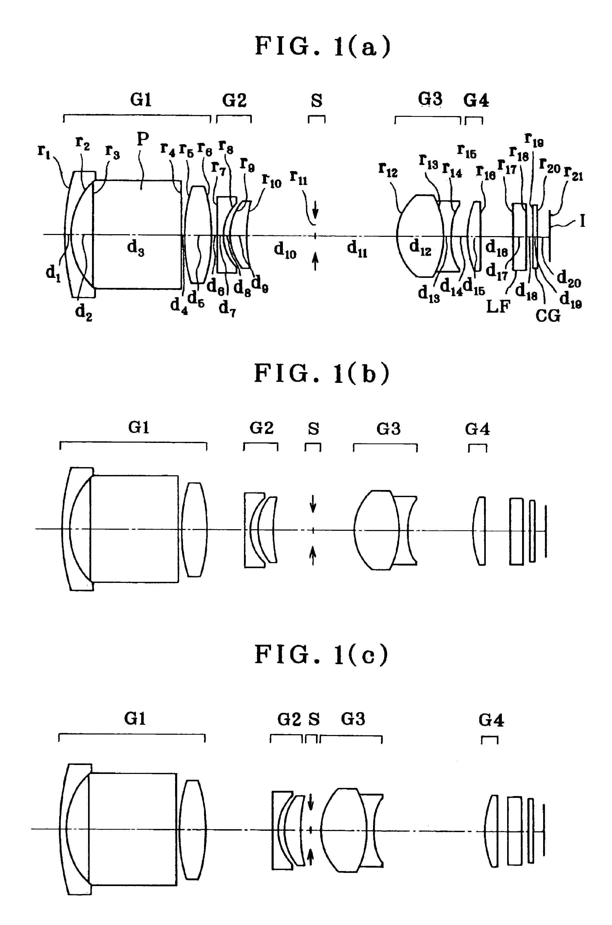
example 1
[0157]
r1 = 31.0100d1 = 1.0000nd1 = 1.80100νd1 = 34.97r2 = 9.9641d2 = 2.9000r3 = ∞d3 = 12.0000nd2 = 1.80610νd2 = 40.92r4 = ∞d4 = 0.3000r5 = 23.6950d5 = 3.5400nd3 = 1.74100νd3 = 52.64r6 = −23.6475d6 = (Variable)r7 = −377.9014d7 = 0.8000nd4 = 1.80610νd4 = 40.92(Aspheric)r8 = 6.4536 (Aspheric)d8 = 0.7000r9 = 6.8913d9 = 2.2000nd5 = 1.75520νd5 = 27.51r10 = 16.1043d10 = (Variable)r11 = ∞ (Stop)d11 = (Variable)r12 = 7.5543d12 = 6.1695nd6 = 1.74320νd6 = 49.34(Aspheric)r13 = −13.0000d13 = 1.0000nd7 = 1.84666νd7 = 23.78r14 = 13.1848d14 = (Variable)(Aspheric)r15 = 12.3030d15 = 1.8000nd8 = 1.74320νd8 = 49.34(Aspheric)r16 = 1061.3553d16 = (Variable)r17 = ∞d17 = 1.9000nd9 = 1.54771νd9 = 62.84r18 = ∞d18 = 0.8000r19 = ∞d19 = 0.7500nd10 = 1.51633νd10 = 64.14r20 = ∞d20 = 1.3565r21 = ∞ (Image Plane)Aspherical Coefficients7th surfaceK = 0A4 = 5.2999 × 10⁻⁴A6 = −2.1607 × 10⁻⁵A8 = 1.8300 × 10⁻⁷A10 = 0.00008th surfaceK = 0A4 = 5.8050 × 10⁻⁴A6 = −1.0603 × 10⁻⁵A8 = −7.5526 × 10⁻⁷A10 = 0.000012th surfaceK = 0...
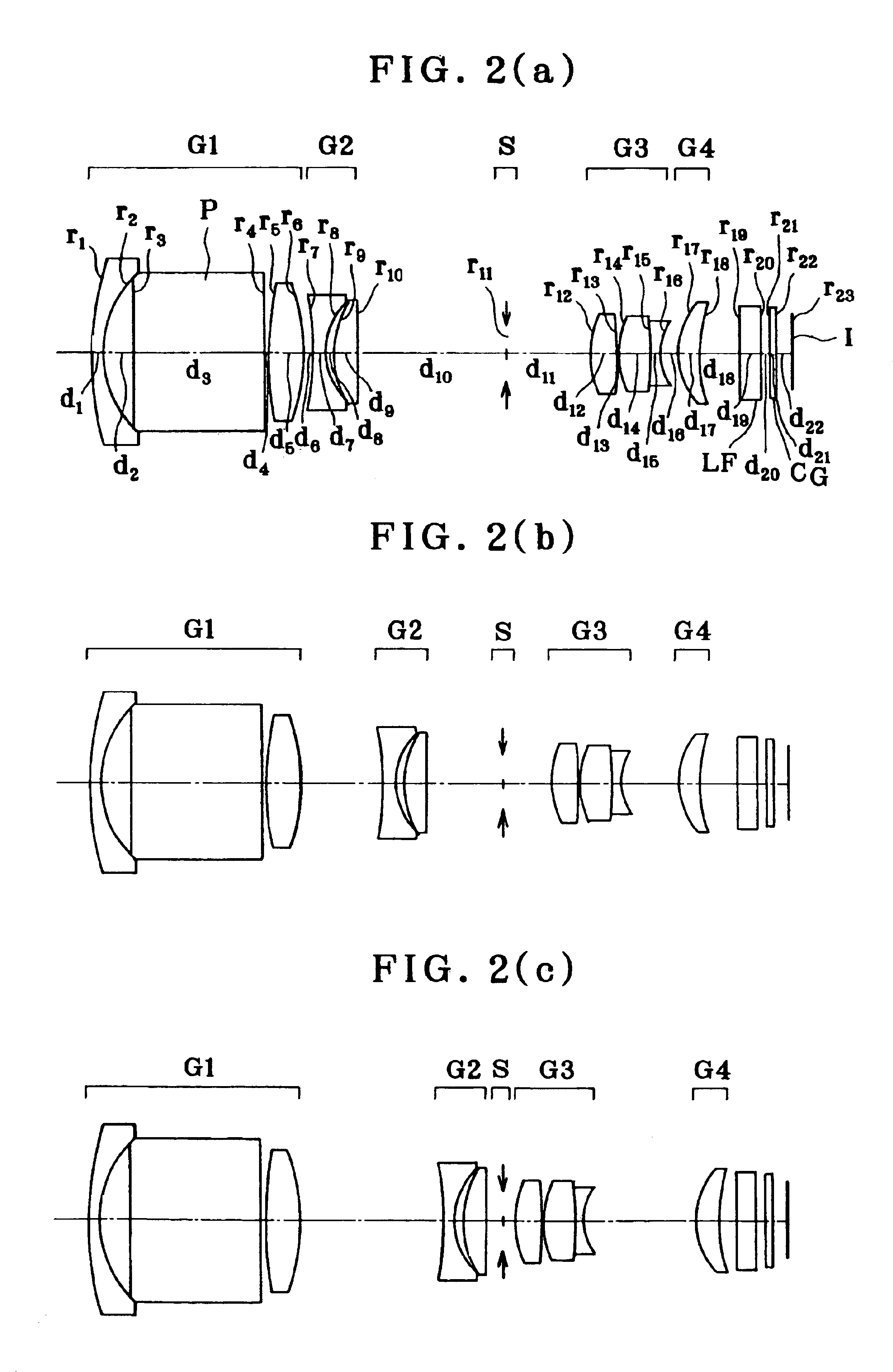
example 2
[0158]
r1 = 31.1674d1 = 1.0000nd1 = 1.80518νd1 = 25.42r2 = 10.0082d2 = 2.8000r3 = ∞d3 = 12.0000nd2 = 1.80610νd2 = 40.92r4 = ∞d4 = 0.3000r5 = 38.3752d5 = 3.3000nd3 = 1.77250νd3 = 49.60r6 = −19.0539d6 = (Variable)r7 = −27.7782d7 = 1.0000nd4 = 1.80610νd4 = 40.92r8 = 5.9968 (Aspheric)d8 = 0.7000r9 = 8.0742d9 = 2.3000nd5 = 1.75520νd5 = 27.51r10 = −358.1053d10 = (Variable)r11 = ∞ (Stop)d11 = (Variable)r12 = 8.4600d12 = 2.5000nd6 = 1.74320νd6 = 49.34(Aspheric)r13 = −116.7590d13 = 0.1500(Aspheric)r14 = 8.8060d14 = 3.0000nd7 = 1.60311νd7 = 60.64r15 = −40.0000d15 = 0.7000nd8 = 1.84666νd8 = 23.78r16 = 4.6054d16 = (Variable)r17 = 6.7337d17 = 1.9700nd9 = 1.69350νd9 = 53.21(Aspheric)r18 = 14.1820d18 = (Variable)r19 = ∞d19 = 1.9000nd10 = 1.54771νd10 = 62.84r20 = ∞d20 = 0.8000r21 = ∞d21 = 0.7500nd11 = 1.51633νd11 = 64.14r22 = ∞d22 = 1.3596r23 = ∞ (Image Plane)Aspherical Coefficients8th surfaceK = 0A4 = −2.7926 × 10⁻⁴A6 = −5.5281 × 10⁻⁶A8 = −3.0031 × 10⁻⁷A10 = 0.000012th surfaceK = 0A4 = −1.0549 × 10...
example 3
[0159]
r1 = 31.4475d1 = 1.0000nd1 = 1.80518νd1 = 25.42r2 = 10.0029d2 = 2.8000r3 = ∞d3 = 12.0000nd2 = 1.80610νd2 = 40.92r4 = ∞d4 = 0.3000r5 = 40.9109d5 = 3.1000nd3 = 1.77250νd3 = 49.60r6 = −18.5523d6 = (Variable)r7 = −27.7365d7 = 0.9000nd4 = 1.80610νd4 = 40.92r8 = 6.1675 (Aspheric)d8 = 0.6000r9 = 7.8689d9 = 2.5000nd5 = 1.75520νd5 = 27.51r10 = 541.9130d10 = (Variable)r11 = ∞ (Stop)d11 = (Variable)r12 = 6.8303d12 = 2.2000nd6 = 1.74320νd6 = 49.34(Aspheric)r13 = −168.3254d13 = 0.1500(Aspheric)r14 = 10.3767d14 = 2.5000nd7 = 1.60311νd7 = 60.64r15 = −100.0000d15 = 0.7000nd8 = 1.84666νd8 = 23.78r16 = 4.2552d16 = (Variable)r17 = 6.4363d17 = 2.0000nd9 = 1.58313νd9 = 59.38(Aspheric)r18 = 16.8235d18 = (Variable)r19 = ∞d19 = 1.5000nd10 = 1.54771νd10 = 62.84r20 = ∞d20 = 0.8000r21 = ∞d21 = 0.7500nd11 = 1.51633νd11 = 64.14r22 = ∞d22 = 1.3596r23 = ∞ (Image Plane)Aspherical Coefficients8th surfaceK = 0A4 = −2.1223 × 10⁻⁴A6 = −3.9476 × 10⁻⁶A8 = −2.3492 × 10⁻⁷A10 = 0.000012th surfaceK = 0A4 = −9.9966 × 1...
PUM
 Abstract
Description
Claims
Application Information